
How to Use maxi fuse: Examples, Pinouts, and Specs
 Design with maxi fuse in Cirkit Designer
Introduction
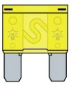
A maxi fuse is a type of automotive fuse designed to protect electrical circuits from overloads and short circuits. It is characterized by its larger size and higher current rating compared to standard fuses, making it ideal for high-power applications. Maxi fuses are commonly used in vehicles, trucks, and other heavy-duty equipment where robust circuit protection is required.
Explore Projects Built with maxi fuse
 Open Project in Cirkit Designer
 Open Project in Cirkit Designer
 Open Project in Cirkit Designer
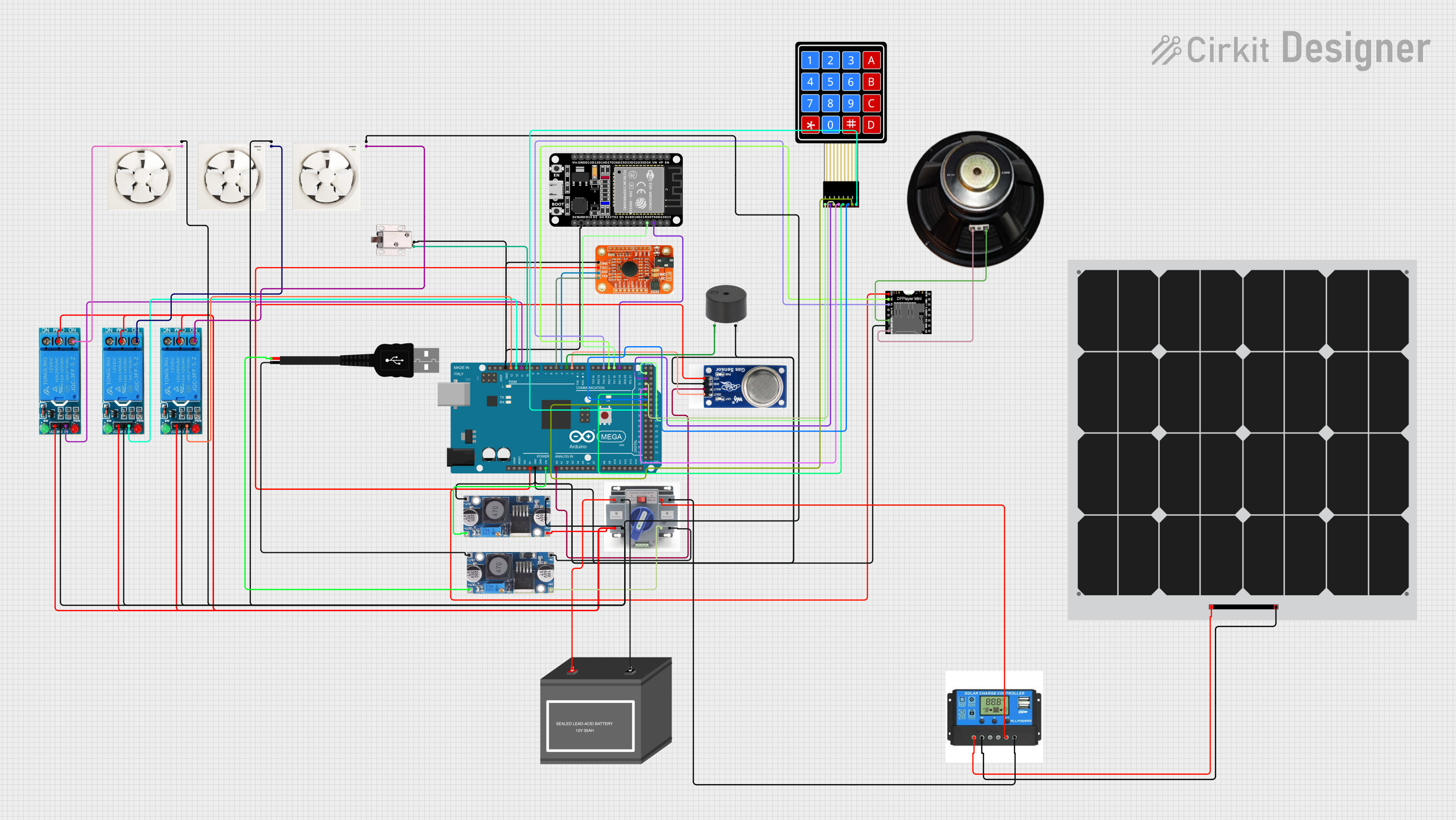 Open Project in Cirkit Designer
Explore Projects Built with maxi fuse
Open Project in Cirkit DesignerOpen Project in Cirkit DesignerOpen Project in Cirkit DesignerOpen Project in Cirkit DesignerCommon Applications and Use Cases
- Automotive electrical systems (e.g., headlights, cooling fans, and audio systems)
- Heavy-duty vehicles and machinery
- Marine and RV electrical systems
- High-current circuits in industrial equipment
- Battery and alternator protection
Technical Specifications
Below are the key technical details of a typical maxi fuse:
| Parameter | Specification |
|---|---|
| Voltage Rating | 32V DC (typical) |
| Current Ratings | 20A to 120A (varies by model) |
| Fuse Type | Blade-style, time-delay fuse |
| Material | Plastic housing with metal terminals |
| Operating Temperature | -40°C to +125°C |
| Dimensions | 29.2mm x 8.5mm x 34.3mm (L x W x H) |
Pin Configuration and Descriptions
Maxi fuses have two blade terminals that connect to the circuit. The table below describes the terminals:
| Pin | Description |
|---|---|
| Blade 1 | Connects to the power source (e.g., battery) |
| Blade 2 | Connects to the load (e.g., electrical device) |
Usage Instructions
How to Use the Maxi Fuse in a Circuit
- Determine the Current Rating: Select a maxi fuse with a current rating slightly higher than the normal operating current of the circuit but lower than the maximum current the wiring can handle.
- Insert the Fuse: Place the maxi fuse into a compatible fuse holder or fuse block. Ensure the blades are securely connected to the terminals.
- Connect the Circuit: Wire the fuse holder in series with the circuit you want to protect. Blade 1 should connect to the power source, and Blade 2 should connect to the load.
- Test the Circuit: Power on the circuit and verify that it operates correctly. If the fuse blows, check for short circuits or excessive current draw.
Important Considerations and Best Practices
- Always use a fuse holder designed for maxi fuses to ensure a secure connection.
- Do not exceed the voltage or current rating of the fuse.
- Replace a blown fuse with one of the same rating to avoid damaging the circuit.
- Inspect the fuse regularly for signs of wear, corrosion, or damage.
- Ensure proper ventilation around the fuse to prevent overheating.
Example: Using a Maxi Fuse with an Arduino UNO
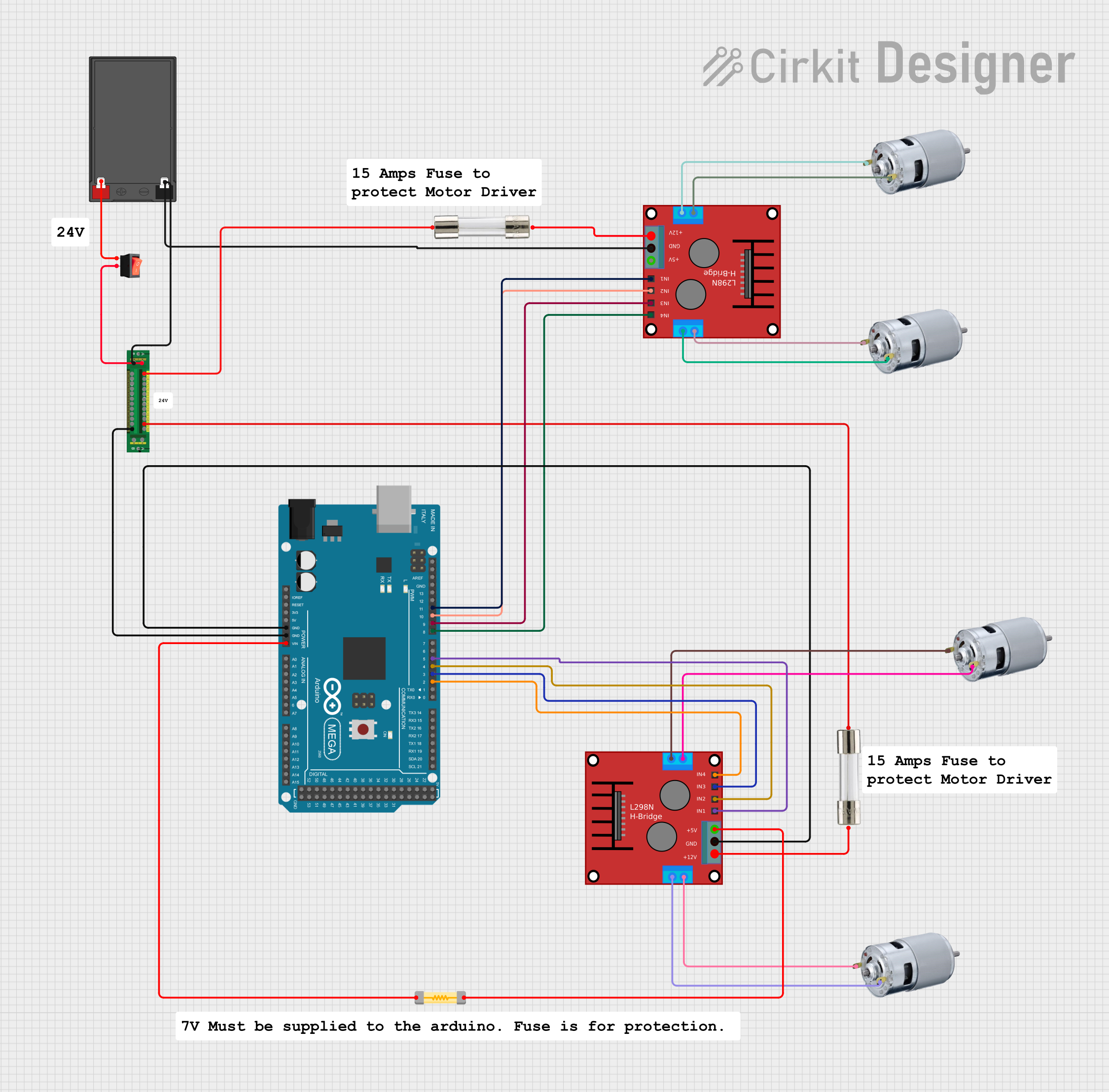
While maxi fuses are not directly connected to microcontrollers like the Arduino UNO, they can be used to protect high-current peripherals in a project. For example, if you are powering a motor or high-power LED strip, you can use a maxi fuse to safeguard the circuit.
// Example Arduino code for controlling a motor with a maxi fuse in the circuit
// Note: The maxi fuse is used to protect the motor circuit, not the Arduino itself.

const int motorPin = 9; // Pin connected to the motor driver

void setup() {
  pinMode(motorPin, OUTPUT); // Set motor pin as output
}

void loop() {
  digitalWrite(motorPin, HIGH); // Turn on the motor
  delay(5000); // Run for 5 seconds
  digitalWrite(motorPin, LOW); // Turn off the motor
  delay(5000); // Wait for 5 seconds
}

// Ensure the maxi fuse is installed in series with the motor circuit to protect
// against overloads or short circuits.
Troubleshooting and FAQs
Common Issues and Solutions
Fuse Blows Repeatedly
- Cause: Circuit is drawing more current than the fuse rating.
- Solution: Check for short circuits or reduce the load on the circuit. Use a fuse with a higher rating if appropriate.
Fuse Does Not Fit in the Holder
- Cause: Incorrect fuse size or incompatible holder.
- Solution: Use a fuse holder specifically designed for maxi fuses.
Corrosion on Fuse Blades
- Cause: Exposure to moisture or poor-quality materials.
- Solution: Replace the fuse and ensure the holder is in a dry, protected location.
Circuit Does Not Power On
- Cause: Blown fuse or loose connections.
- Solution: Inspect the fuse and connections. Replace the fuse if necessary.
FAQs
Q: Can I use a maxi fuse in place of a standard blade fuse?
A: Maxi fuses are larger and have higher current ratings than standard blade fuses. They can be used if the circuit requires higher current protection and the fuse holder is compatible.
Q: How do I know if a maxi fuse is blown?
A: Inspect the fuse element through the transparent housing. If the element is broken or melted, the fuse is blown.
Q: Can I use a maxi fuse for AC circuits?
A: Maxi fuses are designed for DC circuits, typically up to 32V. They are not suitable for AC applications.
Q: What happens if I use a fuse with a higher rating than required?
A: Using a fuse with a higher rating may not protect the circuit effectively, as it may not blow during an overload, potentially causing damage to the wiring or components. Always use the correct rating for your circuit.