How to Use Weigand Keypad: Examples, Pinouts, and Specs
Introduction
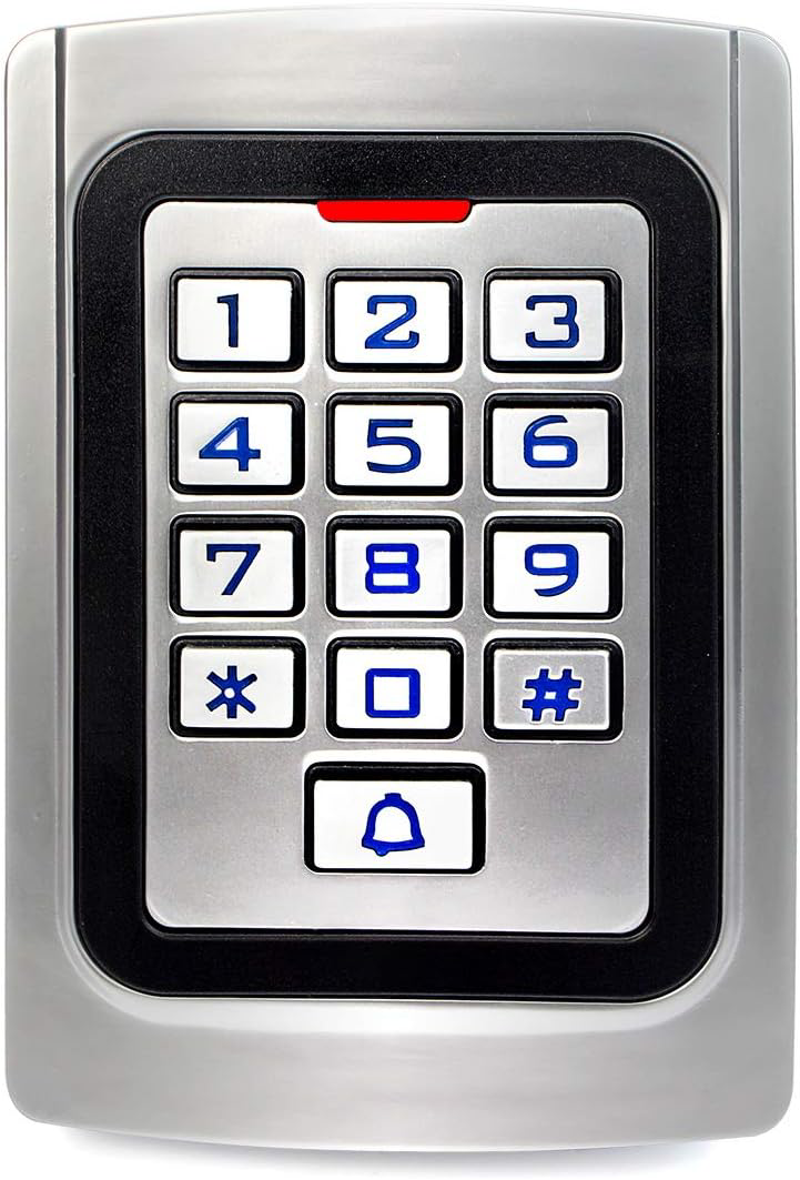
A Weigand keypad is a security device commonly used in access control systems. It allows users to input a numeric code to unlock doors, activate gates, or gain entry to restricted areas. The keypad communicates with access control systems using the Weigand protocol, a widely adopted standard for transmitting data in a secure and reliable format.
Explore Projects Built with Weigand Keypad
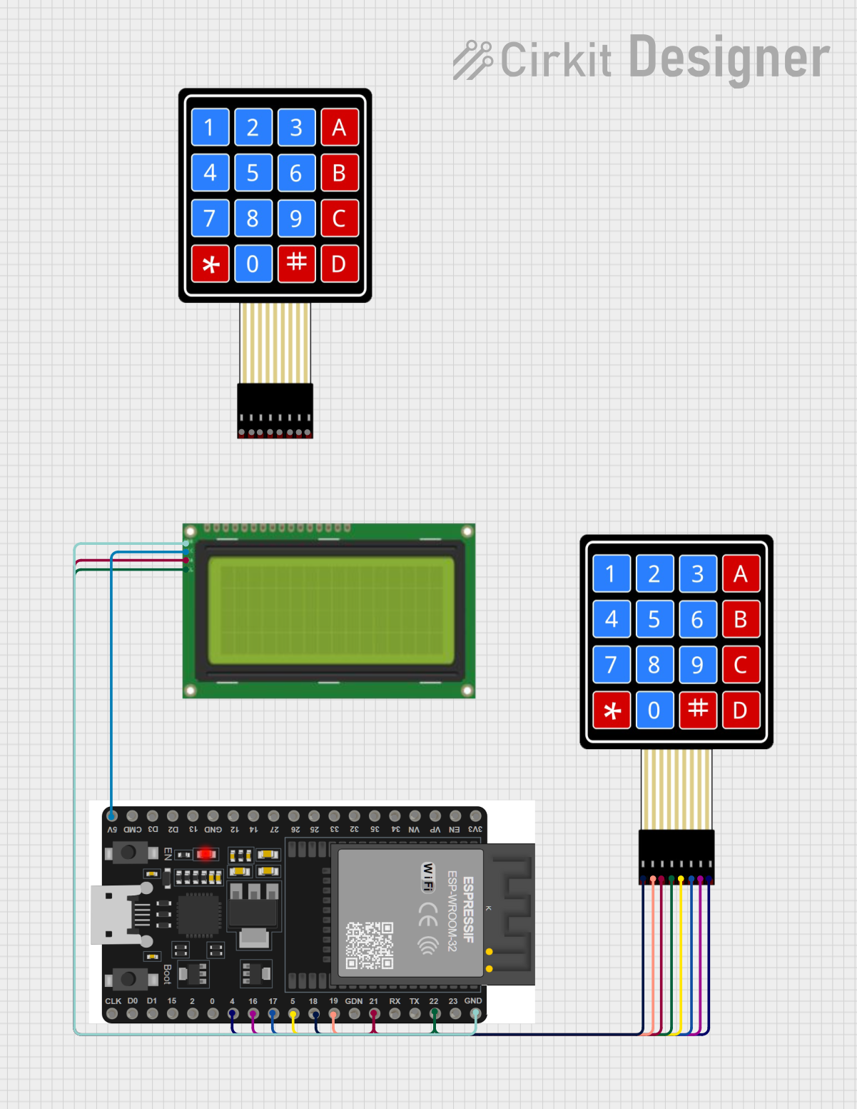
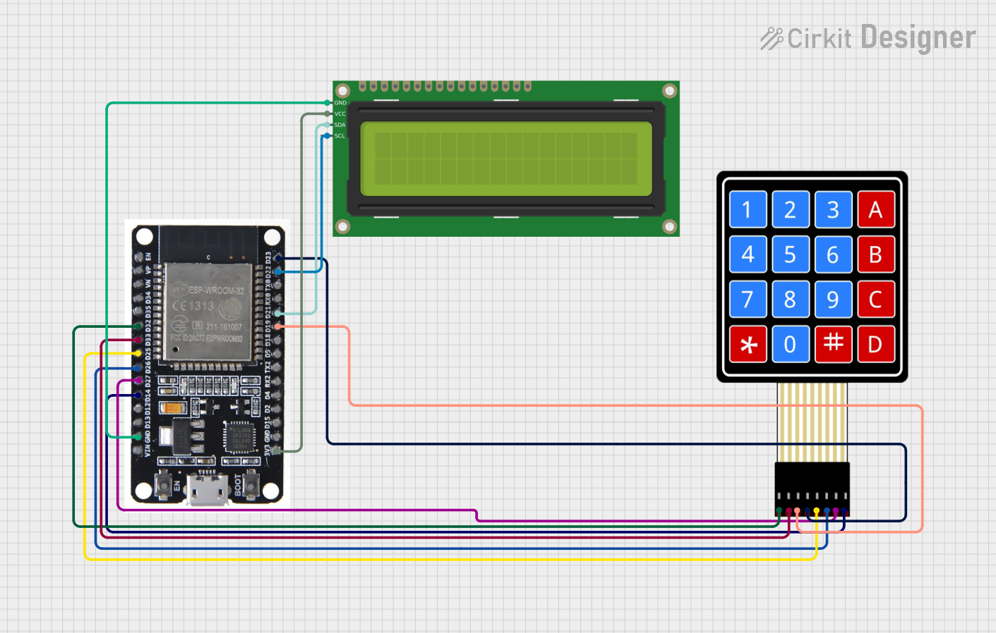
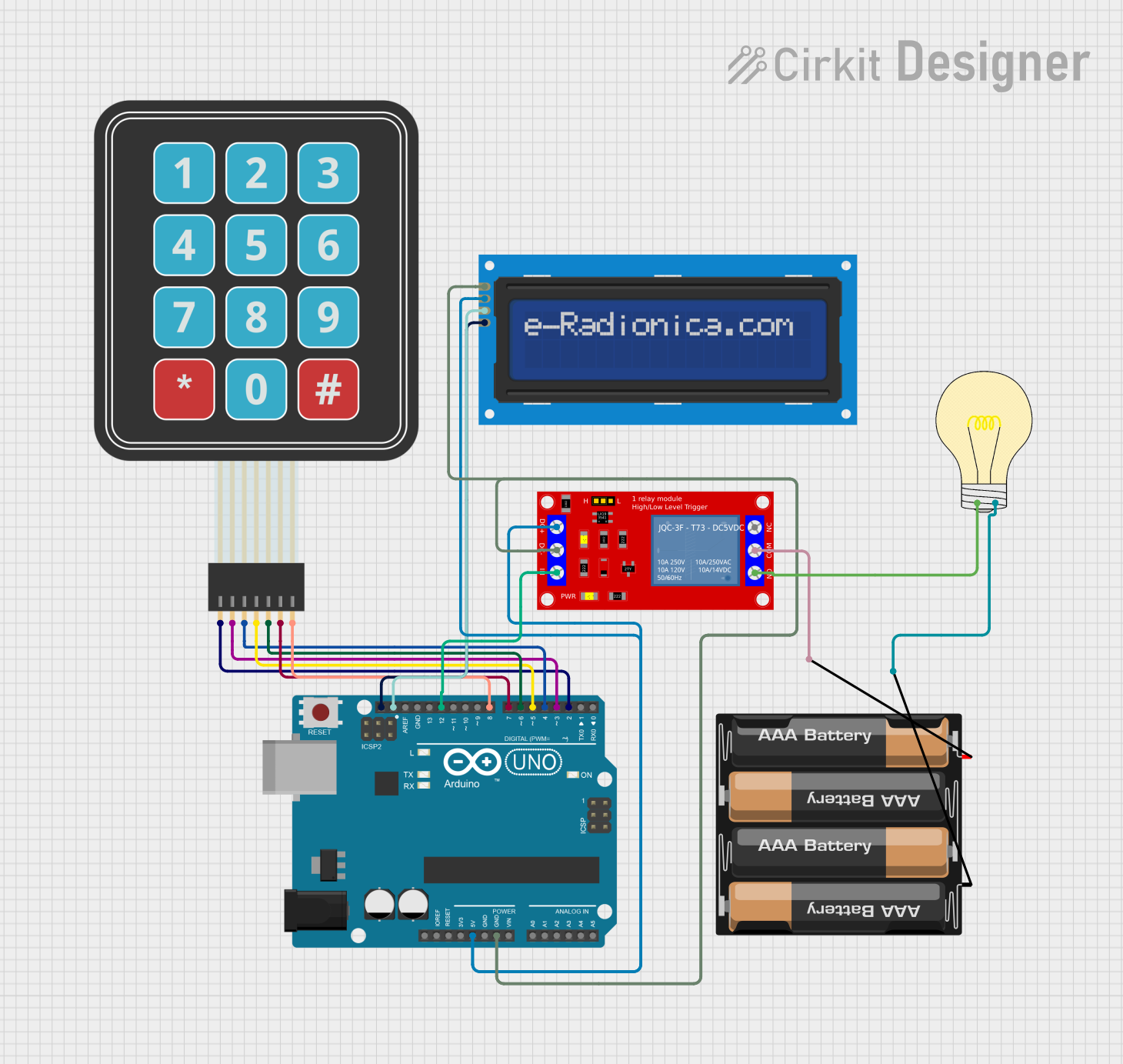
Explore Projects Built with Weigand Keypad
Common Applications and Use Cases
- Door access control in residential and commercial buildings
- Secure entry for parking lots and garages
- Integration with alarm systems for enhanced security
- Multi-factor authentication when combined with RFID readers or biometric devices
Technical Specifications
Key Technical Details
- Operating Voltage: 5V to 12V DC
- Current Consumption: Typically 30mA (standby), up to 100mA (active)
- Communication Protocol: Weigand (commonly Wiegand-26 or Wiegand-34)
- Keypad Type: 3x4 or 4x4 matrix (12 or 16 keys)
- Output Format: Binary data transmitted as pulses (D0 and D1 lines)
- Operating Temperature: -20°C to 60°C
- Housing: Weather-resistant (varies by model)
Pin Configuration and Descriptions
Below is the typical pinout for a Weigand keypad. Note that specific models may vary slightly, so always refer to the manufacturer's datasheet.
| Pin | Name | Description |
|---|---|---|
| 1 | VCC | Power supply input (5V to 12V DC) |
| 2 | GND | Ground connection |
| 3 | D0 | Data 0 line (Weigand protocol output) |
| 4 | D1 | Data 1 line (Weigand protocol output) |
| 5 | LED | LED control input (optional, used to control the keypad's indicator light) |
| 6 | Buzzer | Buzzer control input (optional, used to activate the keypad's buzzer) |
Usage Instructions
How to Use the Component in a Circuit
- Power the Keypad: Connect the VCC pin to a 5V or 12V DC power source and the GND pin to the ground.
- Connect Data Lines:
- Connect the D0 and D1 pins to the corresponding data input pins of your microcontroller or access control system.
- These lines transmit binary data pulses representing the keypresses.
- Optional Connections:
- Use the LED pin to control the keypad's indicator light (e.g., to show access granted or denied).
- Use the Buzzer pin to activate the keypad's buzzer for feedback on keypresses.
- Program the Microcontroller: If using a microcontroller like an Arduino UNO, write code to decode the Weigand data format and process the keypresses.
Important Considerations and Best Practices
- Voltage Compatibility: Ensure the keypad's operating voltage matches your system's power supply.
- Cable Length: Keep the cable length between the keypad and the controller as short as possible to avoid signal degradation.
- Debouncing: Implement software debouncing to filter out noise or unintended keypresses.
- Security: Use the keypad in conjunction with other security measures (e.g., RFID or biometrics) for enhanced protection.
Example Code for Arduino UNO
Below is an example of how to interface a Weigand keypad with an Arduino UNO. This code reads the D0 and D1 lines and decodes the Weigand data.
// Weigand Keypad Example for Arduino UNO
// This code reads data from the D0 and D1 lines of a Weigand keypad
// and prints the decoded keypress to the Serial Monitor.

#define D0_PIN 2  // Connect D0 line to Arduino digital pin 2
#define D1_PIN 3  // Connect D1 line to Arduino digital pin 3

volatile unsigned long weigandData = 0; // Stores the received data
volatile int bitCount = 0;             // Tracks the number of bits received

void setup() {
  pinMode(D0_PIN, INPUT);  // Set D0 pin as input
  pinMode(D1_PIN, INPUT);  // Set D1 pin as input
  attachInterrupt(digitalPinToInterrupt(D0_PIN), handleD0, FALLING);
  attachInterrupt(digitalPinToInterrupt(D1_PIN), handleD1, FALLING);
  Serial.begin(9600);      // Initialize Serial Monitor
}

void loop() {
  if (bitCount == 26) {    // Check if 26 bits (Wiegand-26) have been received
    Serial.print("Keypress detected: ");
    Serial.println(weigandData, HEX); // Print the received data in hexadecimal
    weigandData = 0;        // Reset data
    bitCount = 0;           // Reset bit count
  }
}

// Interrupt service routine for D0 line
void handleD0() {
  weigandData = (weigandData << 1); // Shift left and append 0
  bitCount++;
}

// Interrupt service routine for D1 line
void handleD1() {
  weigandData = (weigandData << 1) | 1; // Shift left and append 1
  bitCount++;
}
Troubleshooting and FAQs
Common Issues and Solutions
No Data Received:
- Cause: Incorrect wiring or loose connections.
- Solution: Double-check all connections, especially the D0 and D1 lines.
Incorrect Keypresses Detected:
- Cause: Signal noise or interference.
- Solution: Use shielded cables and keep the wiring short.
Keypad Not Powering On:
- Cause: Insufficient power supply or incorrect voltage.
- Solution: Verify the power supply voltage and current ratings.
LED or Buzzer Not Working:
- Cause: LED or Buzzer pin not connected or improperly configured.
- Solution: Ensure the LED and Buzzer pins are connected to the appropriate control signals.
FAQs
Q: Can I use a Weigand keypad outdoors?
- A: Yes, many Weigand keypads are weather-resistant, but ensure the model you choose is rated for outdoor use.
Q: What is the difference between Wiegand-26 and Wiegand-34?
- A: Wiegand-26 uses 26 bits of data (24 bits for the code and 2 parity bits), while Wiegand-34 uses 34 bits (32 bits for the code and 2 parity bits).
Q: Can I connect multiple Weigand keypads to a single controller?
- A: Yes, but you will need to implement a method to differentiate between the keypads, such as using separate data lines or multiplexers.
Q: How secure is the Weigand protocol?
- A: While the protocol is reliable, it lacks encryption. For higher security, combine it with other authentication methods.