How to Use Control Hub: Examples, Pinouts, and Specs
Introduction
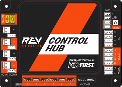
The Control Hub (REV-31-1595) by REV Robotics is a versatile and powerful central unit designed for robotics and automation projects. It serves as the brain of a system, capable of interfacing with a variety of sensors, processing data, and controlling multiple components within a circuit. Common applications include educational robotics platforms, hobbyist projects, and prototype development for industrial automation.
Explore Projects Built with Control Hub

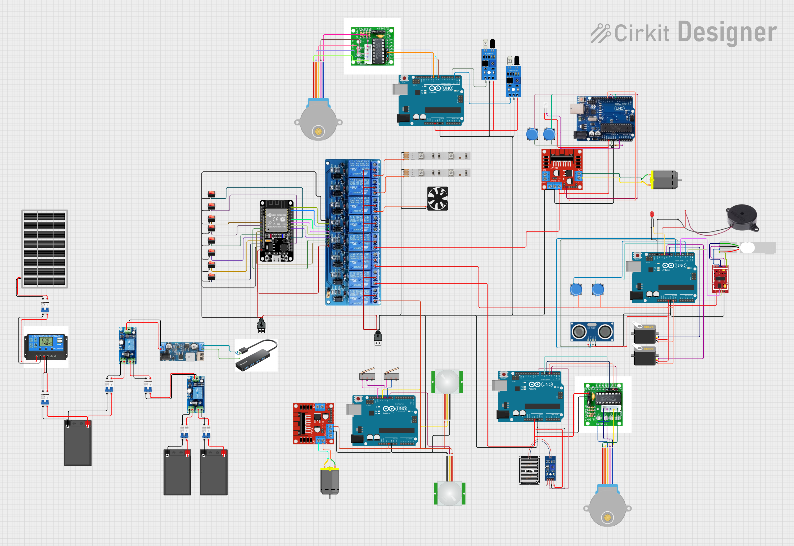
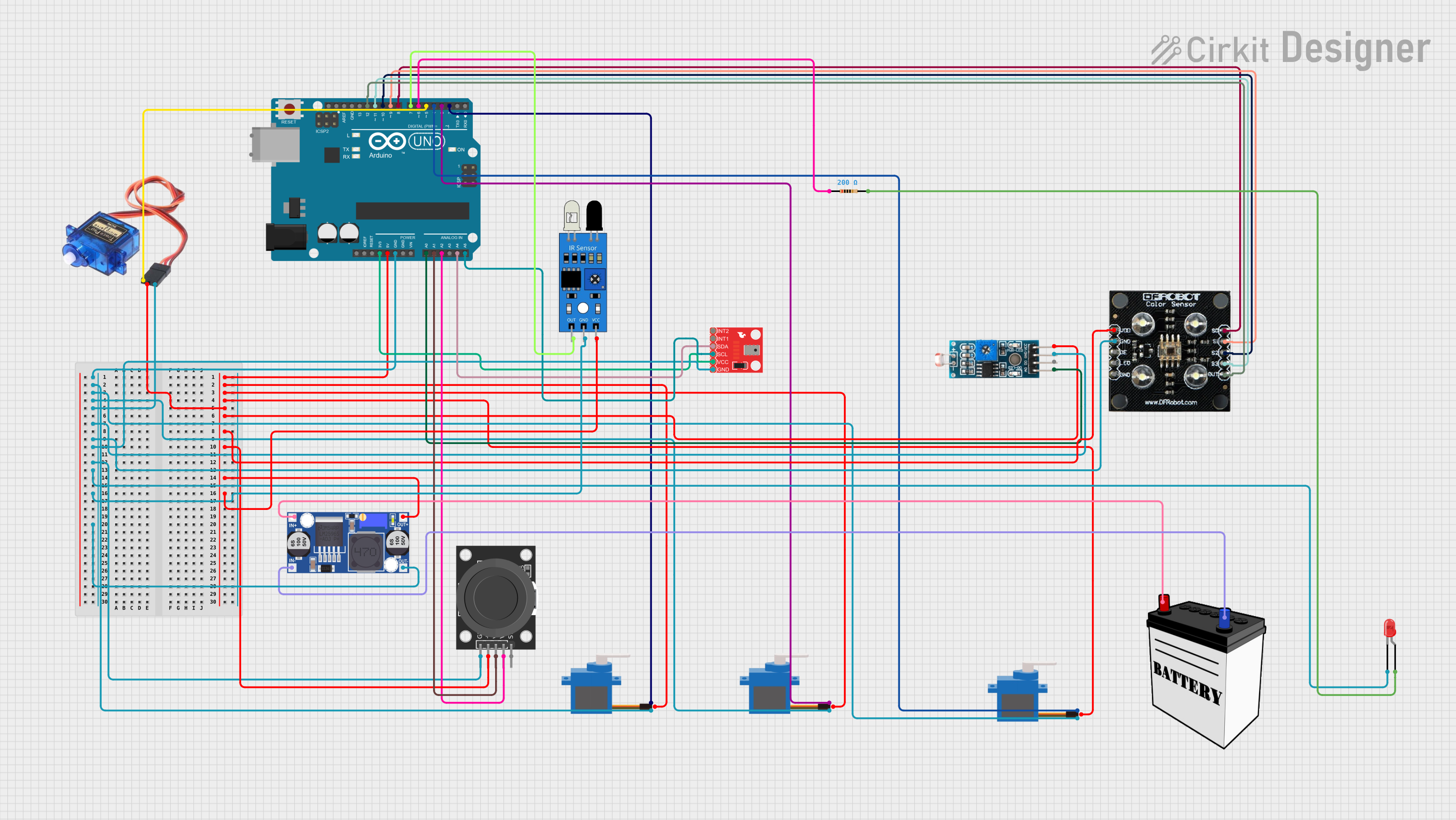

Explore Projects Built with Control Hub
Technical Specifications
Key Technical Details
- Processor: ARM Cortex-A53 (Quad-Core)
- Operating System: Android-based
- Memory: 1 GB RAM, 16 GB eMMC
- Connectivity: Wi-Fi, Bluetooth
- Input Voltage: 12V DC
- Output Ports: Multiple PWM, Digital I/O, Analog Input, I2C, UART, USB
- Dimensions: 110mm x 75mm x 18mm
- Weight: 110g
Pin Configuration and Descriptions
| Pin Number | Description | Type | Notes |
|---|---|---|---|
| 1 | 5V Power Supply | Power | Max 2A output |
| 2 | Ground | Ground | |
| 3-6 | Digital I/O | Digital | Configurable as input or output |
| 7-10 | PWM Output | PWM | For motor and servo control |
| 11-12 | Analog Input | Analog | 0-5V input range |
| 13-14 | I2C Bus | Communication | For I2C compatible devices |
| 15-16 | UART | Communication | Serial communication |
| 17-18 | USB Ports | Communication | For additional peripherals |
Usage Instructions
Integrating the Control Hub into a Circuit
Powering the Control Hub:
- Ensure that the power supply is 12V DC and does not exceed the maximum current rating.
- Connect the positive lead to the 5V power supply pin and the negative lead to the ground pin.
Connecting Sensors and Actuators:
- For digital devices, use the Digital I/O pins.
- For PWM controlled devices like servos, connect to the PWM output pins.
- Analog sensors can be connected to the Analog Input pins.
- I2C devices should be connected to the I2C bus pins, ensuring correct data (SDA) and clock (SCL) lines.
- Serial devices can be interfaced through the UART pins.
Programming the Control Hub:
- The Control Hub can be programmed using the REV Hardware Client or through the Android Studio environment.
- Ensure that the appropriate drivers and software are installed on your development computer.
Best Practices
- Always disconnect the power before making or altering connections.
- Use proper ESD precautions when handling the Control Hub to prevent damage.
- Ensure that all connections are secure to prevent intermittent behavior.
- Avoid placing the Control Hub in environments with extreme temperatures or moisture.
Troubleshooting and FAQs
Common Issues
- Power LED is not lit: Check the power supply and connections.
- Device not recognized by the computer: Ensure that the drivers are installed and the USB cable is functioning.
- Sensors not responding: Verify that the sensor is correctly wired and configured in the software.
FAQs
Q: Can the Control Hub be powered by a battery? A: Yes, as long as the battery provides a stable 12V DC output.
Q: How do I update the firmware on the Control Hub? A: Use the REV Hardware Client to check for and apply firmware updates.
Q: What programming languages are supported? A: The Control Hub supports Java for Android development.
Q: Can the Control Hub be used with an Arduino UNO? A: While the Control Hub is not directly compatible with Arduino hardware, it can communicate with an Arduino UNO via UART or I2C for extended functionality.
Example Code for Arduino UNO Communication
// Example code for communicating between Arduino UNO and Control Hub
#include <Wire.h>

void setup() {
  // Start the I2C bus as a master
  Wire.begin();
  // Start serial communication for debugging
  Serial.begin(9600);
}

void loop() {
  // Send a message to the Control Hub
  Wire.beginTransmission(0x04); // Control Hub I2C address
  Wire.write("Hello, Control Hub!");
  Wire.endTransmission();

  delay(1000); // Wait for a second
}
Note: The I2C address for the Control Hub should be set according to your specific setup.
For further assistance, please refer to the manufacturer's documentation or contact REV Robotics support.