
How to Use Screen: Examples, Pinouts, and Specs
 Design with Screen in Cirkit Designer
Introduction
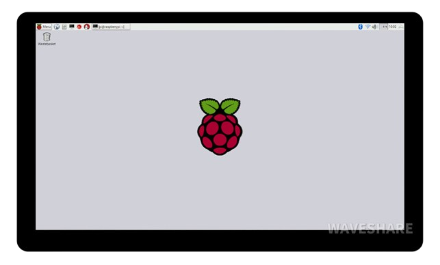
A screen is a display device that visually presents information, images, or video output from a computer or electronic device. Screens are essential components in a wide range of applications, including consumer electronics, industrial systems, and embedded devices. They come in various types, such as LCD, OLED, and TFT, each offering unique advantages depending on the use case.
Common applications of screens include:
- Displaying user interfaces in embedded systems
- Visualizing data in industrial control systems
- Presenting multimedia content in consumer electronics
- Providing feedback in IoT devices
Explore Projects Built with Screen
 Open Project in Cirkit Designer
 Open Project in Cirkit Designer
 Open Project in Cirkit Designer
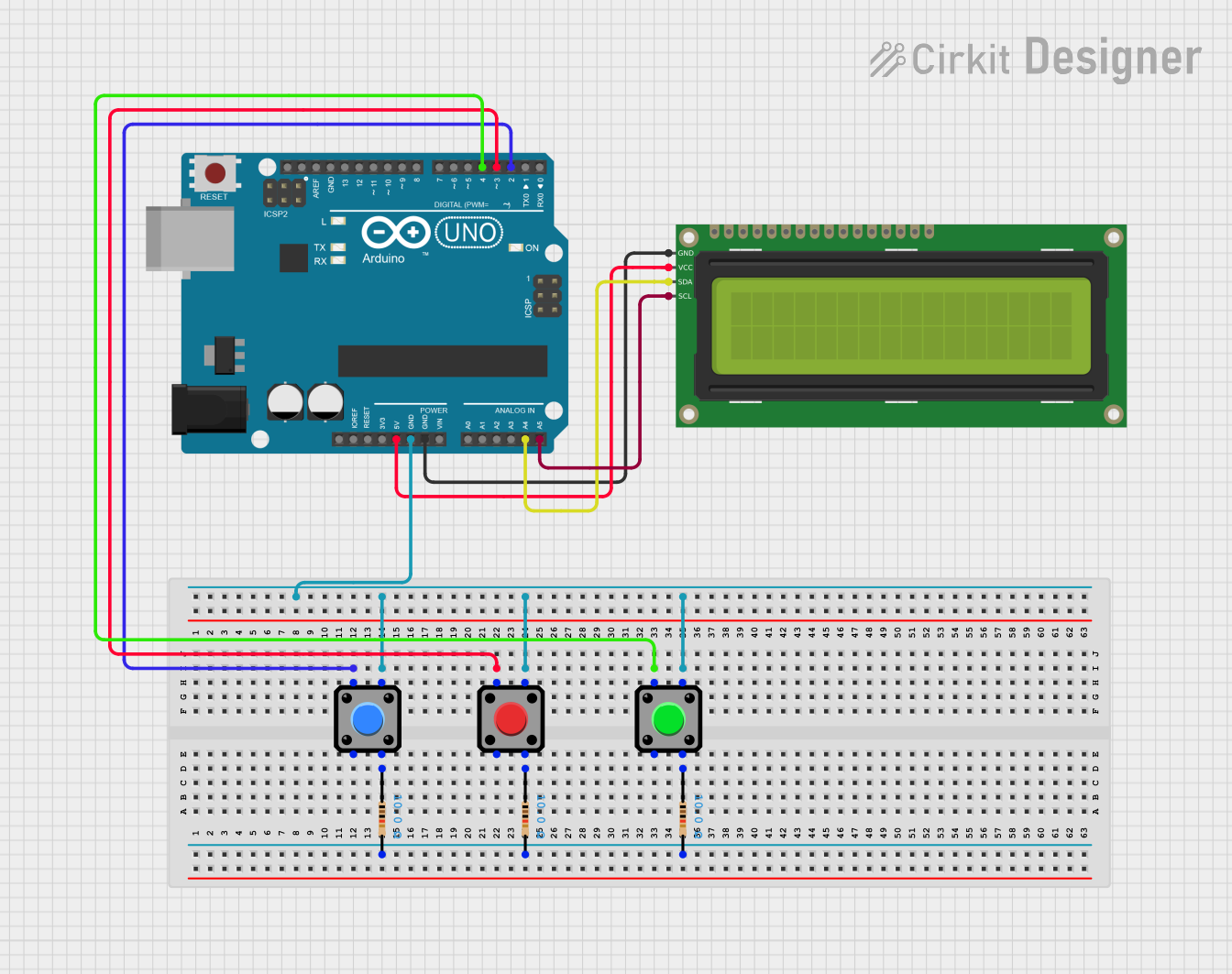 Open Project in Cirkit Designer
Explore Projects Built with Screen
Open Project in Cirkit DesignerOpen Project in Cirkit DesignerOpen Project in Cirkit DesignerOpen Project in Cirkit DesignerTechnical Specifications
The technical specifications of a screen can vary depending on its type and size. Below is an example of a typical 2.4-inch TFT LCD screen:
General Specifications
| Parameter | Value |
|---|---|
| Screen Type | TFT LCD |
| Screen Size | 2.4 inches |
| Resolution | 240 x 320 pixels |
| Color Depth | 16-bit (65,536 colors) |
| Interface | SPI (Serial Peripheral Interface) |
| Operating Voltage | 3.3V |
| Backlight Voltage | 3.0V to 3.6V |
| Current Consumption | ~50mA (with backlight on) |
Pin Configuration
| Pin Number | Pin Name | Description |
|---|---|---|
| 1 | VCC | Power supply (3.3V) |
| 2 | GND | Ground |
| 3 | CS | Chip Select (active low) |
| 4 | RESET | Reset pin (active low) |
| 5 | DC | Data/Command control pin |
| 6 | MOSI | Master Out Slave In (SPI data input) |
| 7 | SCK | Serial Clock (SPI clock input) |
| 8 | LED | Backlight control (connect to 3.3V or PWM pin) |
Usage Instructions
How to Use the Screen in a Circuit
- Power Supply: Connect the
VCCpin to a 3.3V power source and theGNDpin to ground. - SPI Communication: Connect the
CS,RESET,DC,MOSI, andSCKpins to the corresponding SPI pins on your microcontroller. - Backlight Control: Connect the
LEDpin to a 3.3V source or a PWM pin for brightness control. - Initialization: Use a suitable library (e.g., Adafruit GFX or TFT_eSPI) to initialize and control the screen.
Important Considerations
- Ensure the operating voltage matches the screen's specifications to avoid damage.
- Use level shifters if your microcontroller operates at 5V logic levels.
- Avoid excessive current draw by limiting the backlight brightness if necessary.
- Handle the screen carefully to prevent damage to the display surface.
Example Code for Arduino UNO
Below is an example of how to use a 2.4-inch TFT LCD screen with an Arduino UNO:
#include <Adafruit_GFX.h>    // Core graphics library
#include <Adafruit_TFTLCD.h> // Hardware-specific library for TFT

#define LCD_CS A3  // Chip Select pin
#define LCD_CD A2  // Command/Data pin
#define LCD_WR A1  // LCD Write pin
#define LCD_RD A0  // LCD Read pin
#define LCD_RESET A4 // Reset pin

// Create an instance of the TFT screen
Adafruit_TFTLCD tft(LCD_CS, LCD_CD, LCD_WR, LCD_RD, LCD_RESET);

void setup() {
  tft.reset(); // Reset the screen
  tft.begin(0x9341); // Initialize with the screen's driver ID (e.g., ILI9341)

  tft.fillScreen(0x0000); // Clear the screen (black background)
  tft.setTextColor(0xFFFF); // Set text color to white
  tft.setTextSize(2); // Set text size
  tft.setCursor(10, 10); // Set cursor position
  tft.print("Hello, World!"); // Display text
}

void loop() {
  // Add your code here to update the screen dynamically
}
Notes:
- Replace
0x9341with the correct driver ID for your screen if necessary. - Ensure the wiring matches the pin definitions in the code.
Troubleshooting and FAQs
Common Issues
Screen Not Turning On:
- Verify the power connections and ensure the correct voltage is supplied.
- Check the backlight pin connection.
No Display Output:
- Ensure the SPI connections are correct and match the pin definitions in the code.
- Confirm that the screen's driver ID is correctly specified in the initialization code.
Flickering or Distorted Display:
- Check for loose connections or poor soldering.
- Ensure the SPI clock speed is within the screen's supported range.
Backlight Not Working:
- Verify the backlight pin is connected to a 3.3V source or a PWM pin.
- Check for excessive current draw or a damaged backlight LED.
FAQs
Q: Can I use this screen with a 5V microcontroller?
A: Yes, but you must use level shifters to convert the 5V logic signals to 3.3V to avoid damaging the screen.
Q: How do I control the brightness of the backlight?
A: Connect the LED pin to a PWM-capable pin on your microcontroller and adjust the duty cycle to control brightness.
Q: What library should I use for this screen?
A: The Adafruit GFX and Adafruit TFTLCD libraries are commonly used for TFT screens. Ensure compatibility with your specific screen model.
Q: Can I display images on this screen?
A: Yes, you can display images by converting them to a compatible format (e.g., BMP) and using the appropriate library functions to render them.
By following this documentation, you can effectively integrate and troubleshoot a screen in your electronic projects.