How to Use keypad proteus: Examples, Pinouts, and Specs
Introduction
The Keypad Proteus is a virtual keypad component developed by RAM with the part ID Proteus. It is designed for use in the Proteus simulation software, enabling users to simulate input from a physical keypad in electronic circuit designs. This component is particularly useful for testing and debugging circuits that require user input, such as password-protected systems, menu navigation, or other interactive applications.
Explore Projects Built with keypad proteus

Explore Projects Built with keypad proteus
Common Applications and Use Cases
- Simulating user input for microcontroller-based projects.
- Testing password-protected systems in a virtual environment.
- Debugging circuits that require keypad interaction.
- Designing and simulating menu-driven interfaces.
- Educational purposes for learning keypad interfacing.
Technical Specifications
The Keypad Proteus is a virtual component, so it does not have physical electrical specifications. However, it simulates the behavior of a standard 4x4 matrix keypad. Below are its key details:
Key Features
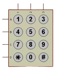
- Matrix Configuration: 4 rows x 4 columns (4x4 matrix).
- Key Count: 16 keys (labeled 0-9, A-D, *, and #).
- Interface: Simulated row and column pins for connection to microcontrollers.
- Software Compatibility: Exclusively used in Proteus simulation software.
Pin Configuration and Descriptions
The Keypad Proteus has 8 pins, corresponding to the rows and columns of the keypad matrix. The pin configuration is as follows:
| Pin Number | Pin Name | Description |
|---|---|---|
| 1 | R1 | Row 1 of the keypad matrix |
| 2 | R2 | Row 2 of the keypad matrix |
| 3 | R3 | Row 3 of the keypad matrix |
| 4 | R4 | Row 4 of the keypad matrix |
| 5 | C1 | Column 1 of the keypad matrix |
| 6 | C2 | Column 2 of the keypad matrix |
| 7 | C3 | Column 3 of the keypad matrix |
| 8 | C4 | Column 4 of the keypad matrix |
Usage Instructions
How to Use the Keypad Proteus in a Circuit
- Add the Component: Open Proteus, search for "Keypad" in the component library, and select the Keypad Proteus component.
- Place the Component: Drag and drop the keypad into your schematic workspace.
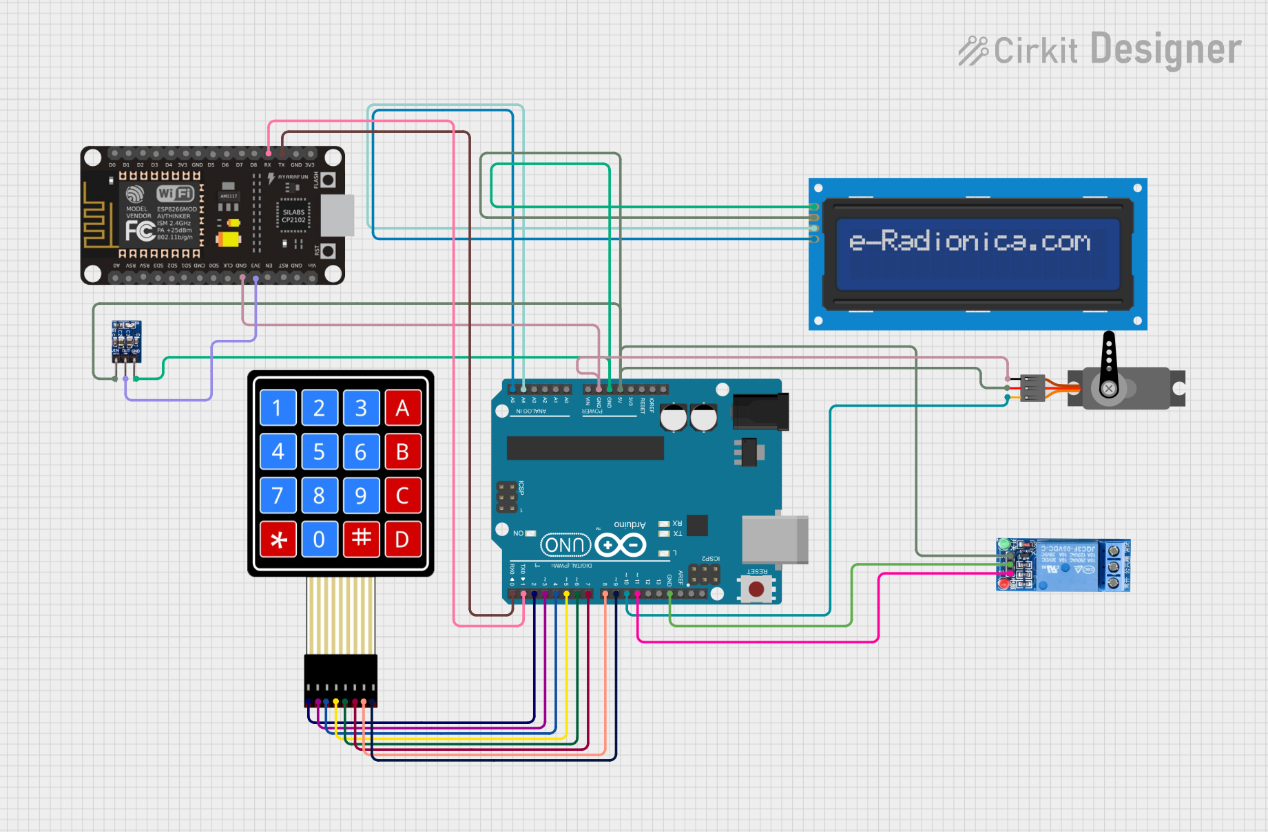
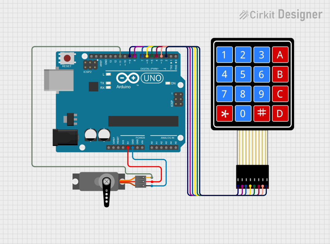
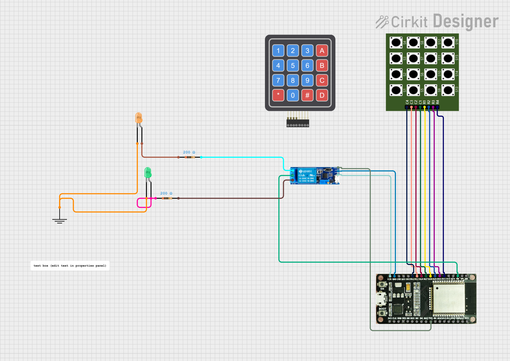
- Connect to a Microcontroller:
- Connect the row pins (R1-R4) and column pins (C1-C4) to the corresponding GPIO pins of your microcontroller.
- Use pull-up or pull-down resistors if required by your microcontroller's configuration.
- Simulate Key Presses:
- During simulation, click on the keys of the virtual keypad to simulate user input.
- The corresponding row and column pins will change their state, allowing the microcontroller to detect the key press.
Important Considerations and Best Practices
- Debouncing: Implement software debouncing in your microcontroller code to avoid false keypress detections.
- Pin Mapping: Ensure the row and column pins are correctly mapped in your microcontroller code to match the keypad's configuration.
- Simulation Limitations: The Keypad Proteus is a virtual component and cannot be used in physical circuits.
Example Code for Arduino UNO
Below is an example of how to interface the Keypad Proteus with an Arduino UNO in Proteus:
#include <Keypad.h> // Include the Keypad library

// Define the rows and columns of the keypad
const byte ROWS = 4; // Four rows
const byte COLS = 4; // Four columns

// Define the keymap for the 4x4 keypad
char keys[ROWS][COLS] = {
  {'1', '2', '3', 'A'},
  {'4', '5', '6', 'B'},
  {'7', '8', '9', 'C'},
  {'*', '0', '#', 'D'}
};

// Define the row and column pins connected to the Arduino
byte rowPins[ROWS] = {9, 8, 7, 6}; // Connect to R1, R2, R3, R4
byte colPins[COLS] = {5, 4, 3, 2}; // Connect to C1, C2, C3, C4

// Create a Keypad object
Keypad keypad = Keypad(makeKeymap(keys), rowPins, colPins, ROWS, COLS);

void setup() {
  Serial.begin(9600); // Initialize serial communication
  Serial.println("Keypad Test: Press a key");
}

void loop() {
  char key = keypad.getKey(); // Get the key pressed
  if (key) {
    // If a key is pressed, print it to the Serial Monitor
    Serial.print("Key Pressed: ");
    Serial.println(key);
  }
}
Notes:
- Ensure the row and column pins in the code match the connections in your Proteus schematic.
- Use the Proteus simulation to observe the serial output when keys are pressed.
Troubleshooting and FAQs
Common Issues and Solutions
Key Presses Not Detected:
- Ensure the row and column pins are correctly connected to the microcontroller in the Proteus schematic.
- Verify that the pin mappings in your code match the schematic.
Multiple Key Presses Detected:
- Implement software debouncing in your code to filter out false keypresses.
Simulation Not Responding to Key Presses:
- Ensure the simulation is running in Proteus.
- Check that the keypad is properly connected to the microcontroller in the schematic.
FAQs
Q: Can I use the Keypad Proteus in a physical circuit?
A: No, the Keypad Proteus is a virtual component designed exclusively for use in Proteus simulation software.
Q: How do I simulate multiple key presses?
A: In Proteus, you can only simulate one key press at a time by clicking on the virtual keypad. Simulating multiple simultaneous key presses is not supported.
Q: Is the Keypad Proteus compatible with all microcontrollers?
A: Yes, it can be used with any microcontroller supported by Proteus, as long as the microcontroller has sufficient GPIO pins for the keypad interface.
Q: Do I need external pull-up or pull-down resistors?
A: In simulation, pull-up or pull-down resistors are not required. However, in real-world circuits, they may be necessary depending on your microcontroller's configuration.
This concludes the documentation for the Keypad Proteus component.