How to Use TCS3472 COLOR LIGHT-TO-DIGITAL CONVERTER with IR FILTER: Examples, Pinouts, and Specs
Introduction
The TCS3472 is a color light-to-digital converter that includes an integrated infrared (IR) filter, enabling accurate measurement of ambient light and color in various environments. This component features a photodiode array and an analog-to-digital converter (ADC), which work together to detect red, green, blue, and clear (RGBC) light levels and convert them into digital signals. The TCS3472 is widely used in applications requiring precise color sensing, such as display calibration, ambient light sensing, and industrial color matching.
Explore Projects Built with TCS3472 COLOR LIGHT-TO-DIGITAL CONVERTER with IR FILTER
Explore Projects Built with TCS3472 COLOR LIGHT-TO-DIGITAL CONVERTER with IR FILTER
Common Applications
- Display backlight adjustment for mobile devices
- Color matching in industrial processes
- Ambient light sensing for smart lighting systems
- Gesture recognition and proximity sensing (when paired with an IR LED)
Technical Specifications
The TCS3472 is a highly versatile component with the following key specifications:
| Parameter | Value |
|---|---|
| Supply Voltage (VDD) | 2.7V to 3.6V |
| I²C Interface Voltage | 1.8V to 3.6V |
| Operating Current | 235 µA (typical) |
| Sleep Mode Current | 2.5 µA (typical) |
| Spectral Range | Red, Green, Blue, Clear (RGBC) |
| IR Rejection | Integrated IR filter |
| Communication Interface | I²C (7-bit address: 0x29 default) |
| Integration Time | Programmable (2.4 ms to 700 ms) |
| Operating Temperature Range | -30°C to +85°C |
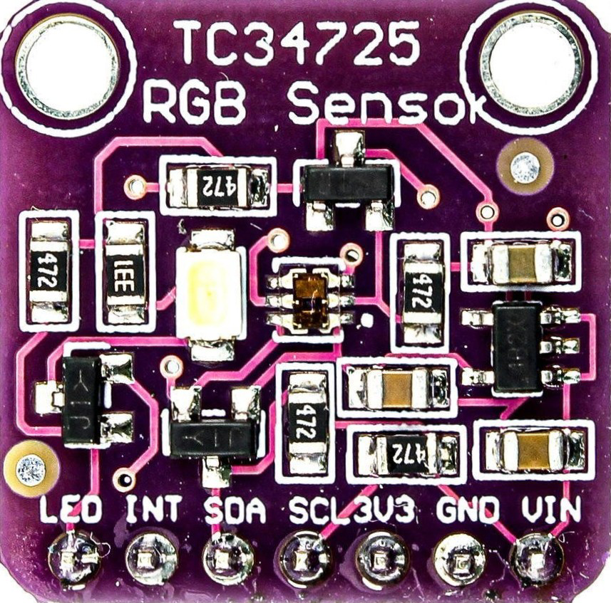
Pin Configuration and Descriptions
The TCS3472 is typically available in an 8-pin package. Below is the pinout and description:
| Pin | Name | Description |
|---|---|---|
| 1 | GND | Ground |
| 2 | SDA | I²C data line |
| 3 | SCL | I²C clock line |
| 4 | INT | Interrupt output (active low, open-drain) |
| 5 | LDR | LED driver output (optional, for external IR LED) |
| 6 | VDD | Power supply (2.7V to 3.6V) |
| 7 | NC | No connection (leave unconnected) |
| 8 | NC | No connection (leave unconnected) |
Usage Instructions
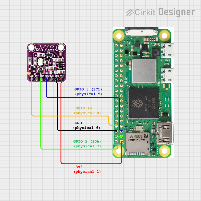
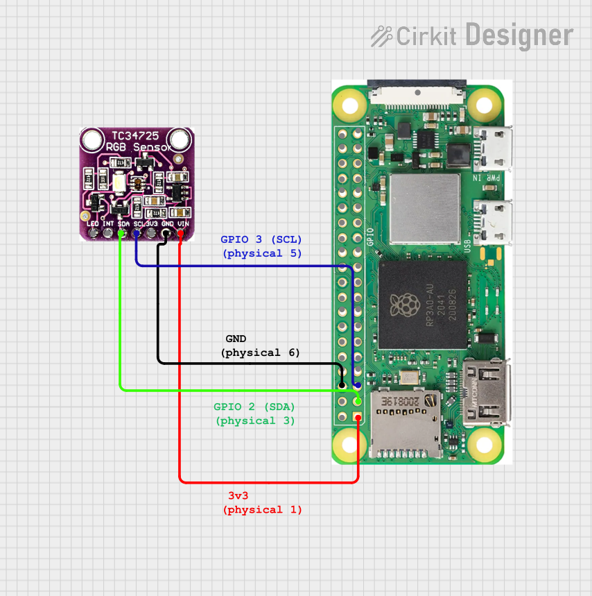
How to Use the TCS3472 in a Circuit
- Power Supply: Connect the VDD pin to a 3.3V power source and the GND pin to ground.
- I²C Communication: Connect the SDA and SCL pins to the corresponding I²C pins on your microcontroller. Use pull-up resistors (typically 4.7 kΩ) on both lines.
- Interrupt Pin (Optional): The INT pin can be connected to a GPIO pin on the microcontroller to handle interrupts for threshold-based events.
- LED Driver (Optional): If using an external IR LED, connect it to the LDR pin for automatic control.
Important Considerations
- I²C Address: The default I²C address of the TCS3472 is 0x29. Ensure no other devices on the I²C bus share this address.
- Integration Time: Adjust the integration time to balance sensitivity and response time. Longer integration times improve accuracy in low-light conditions.
- IR Interference: The integrated IR filter minimizes interference, but avoid placing the sensor near strong IR sources (e.g., sunlight or IR LEDs).
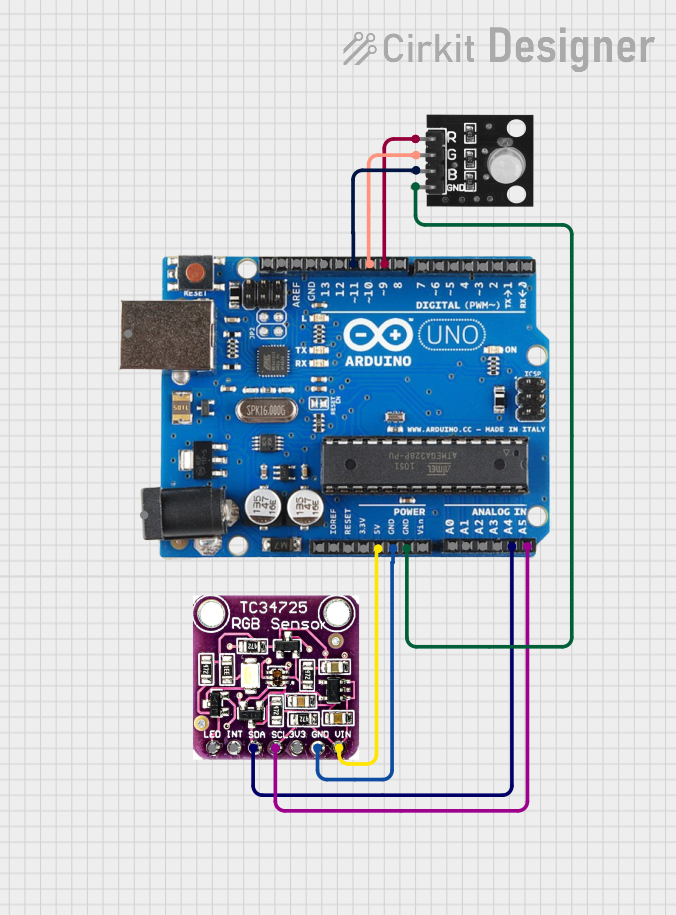
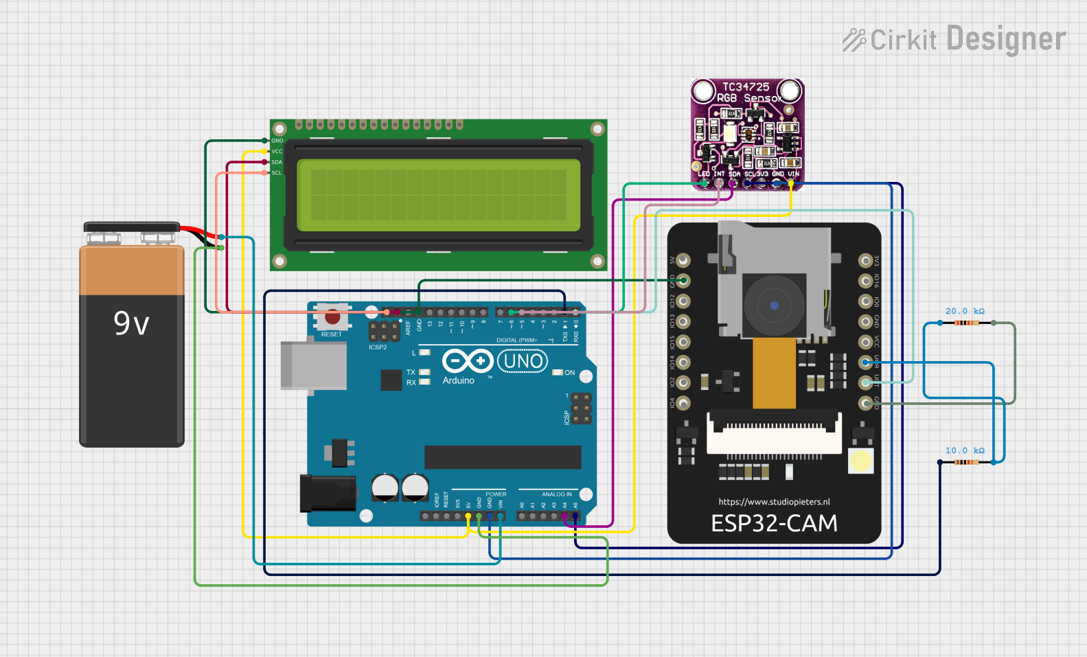
Example Code for Arduino UNO
Below is an example of how to interface the TCS3472 with an Arduino UNO to read RGBC values:
#include <Wire.h>

// TCS3472 I²C address
#define TCS3472_ADDRESS 0x29

// Register addresses
#define ENABLE_REGISTER 0x80
#define RGBC_TIMING_REGISTER 0x81
#define RGBC_DATA_REGISTER 0x94

void setup() {
  Wire.begin(); // Initialize I²C communication
  Serial.begin(9600); // Initialize serial communication for debugging

  // Enable the TCS3472
  Wire.beginTransmission(TCS3472_ADDRESS);
  Wire.write(ENABLE_REGISTER); // Select the enable register
  Wire.write(0x03); // Power on and enable RGBC
  Wire.endTransmission();

  // Set integration time (e.g., 700 ms)
  Wire.beginTransmission(TCS3472_ADDRESS);
  Wire.write(RGBC_TIMING_REGISTER); // Select the RGBC timing register
  Wire.write(0x00); // Maximum integration time
  Wire.endTransmission();
}

void loop() {
  uint16_t red, green, blue, clear;

  // Request RGBC data
  Wire.beginTransmission(TCS3472_ADDRESS);
  Wire.write(RGBC_DATA_REGISTER | 0x80); // Command to read RGBC data
  Wire.endTransmission();
  Wire.requestFrom(TCS3472_ADDRESS, 8); // Request 8 bytes of data

  // Read RGBC values
  clear = Wire.read() | (Wire.read() << 8);
  red = Wire.read() | (Wire.read() << 8);
  green = Wire.read() | (Wire.read() << 8);
  blue = Wire.read() | (Wire.read() << 8);

  // Print the values to the serial monitor
  Serial.print("Red: ");
  Serial.print(red);
  Serial.print(" Green: ");
  Serial.print(green);
  Serial.print(" Blue: ");
  Serial.print(blue);
  Serial.print(" Clear: ");
  Serial.println(clear);

  delay(1000); // Wait 1 second before the next reading
}
Troubleshooting and FAQs
Common Issues
No I²C Communication:
- Ensure the SDA and SCL lines are connected correctly.
- Verify that pull-up resistors are present on the I²C lines.
- Check that the TCS3472 is powered correctly (VDD and GND).
Incorrect or Unstable Readings:
- Verify that the sensor is not exposed to direct sunlight or strong IR sources.
- Ensure the integration time is appropriate for the lighting conditions.
Interrupt Pin Not Working:
- Confirm that the INT pin is connected to a GPIO pin configured as an input.
- Check the interrupt threshold settings in the TCS3472 registers.
FAQs
Q: Can the TCS3472 detect colors in complete darkness?
A: No, the TCS3472 requires ambient light or an external light source to detect colors. You can use an external LED for illumination.
Q: What is the purpose of the IR filter?
A: The IR filter blocks infrared light, which can interfere with accurate color detection, ensuring precise RGBC measurements.
Q: Can I use the TCS3472 with a 5V microcontroller?
A: Yes, but you must use a level shifter to safely interface the 3.3V I²C lines with the 5V microcontroller.