
How to Use RP2040 Debugger: Examples, Pinouts, and Specs
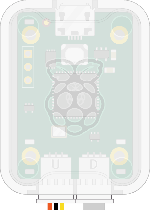
 Design with RP2040 Debugger in Cirkit Designer
Introduction
The RP2040 Debugger is a specialized debugging tool developed by Raspberry Pi for the RP2040 microcontroller. It provides developers with a robust platform to program, debug, and test their applications efficiently. With features such as breakpoints, step execution, and variable inspection, the RP2040 Debugger simplifies the development process and helps identify and resolve issues in embedded systems.
Explore Projects Built with RP2040 Debugger
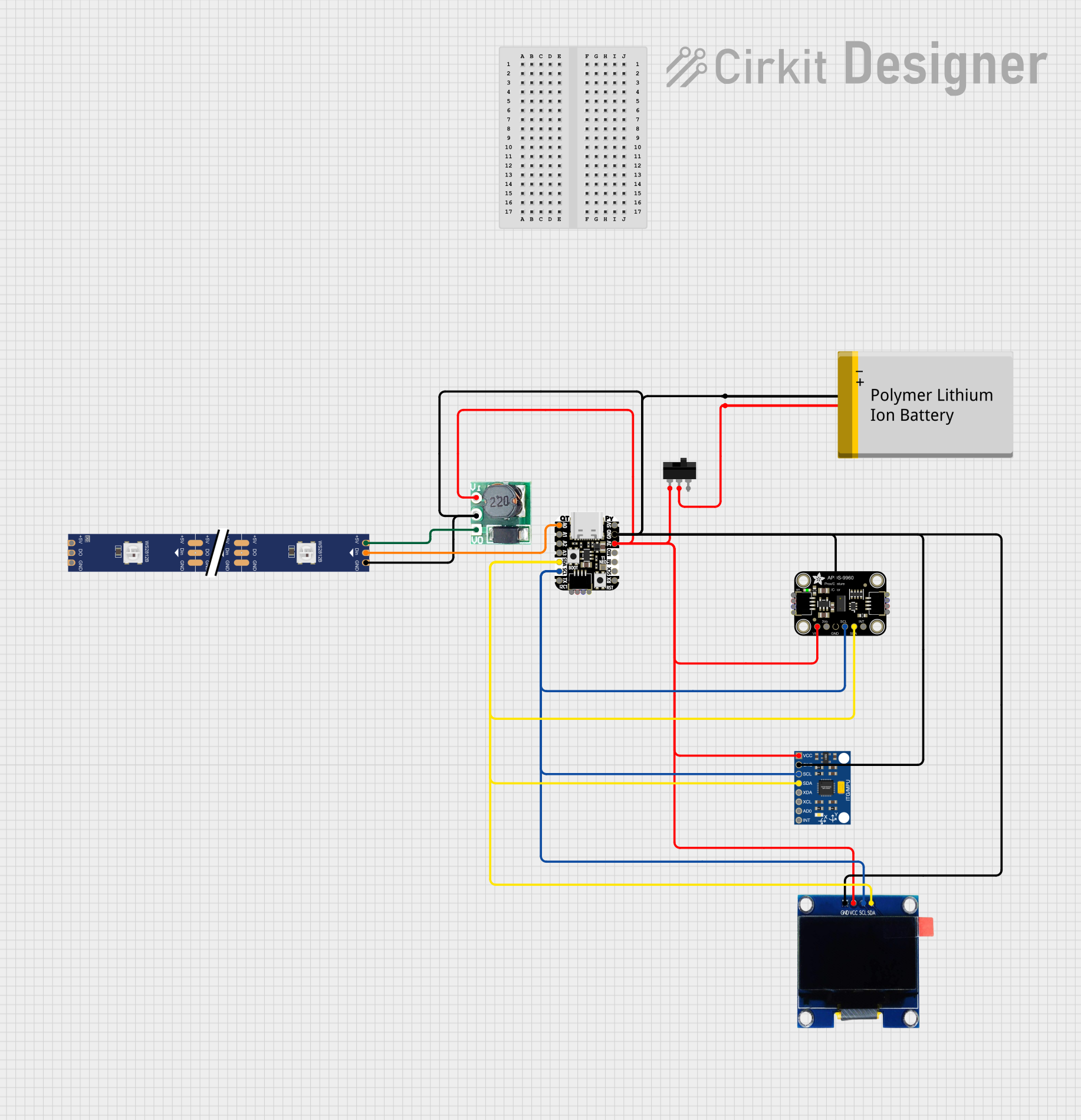
 Open Project in Cirkit Designer
 Open Project in Cirkit Designer
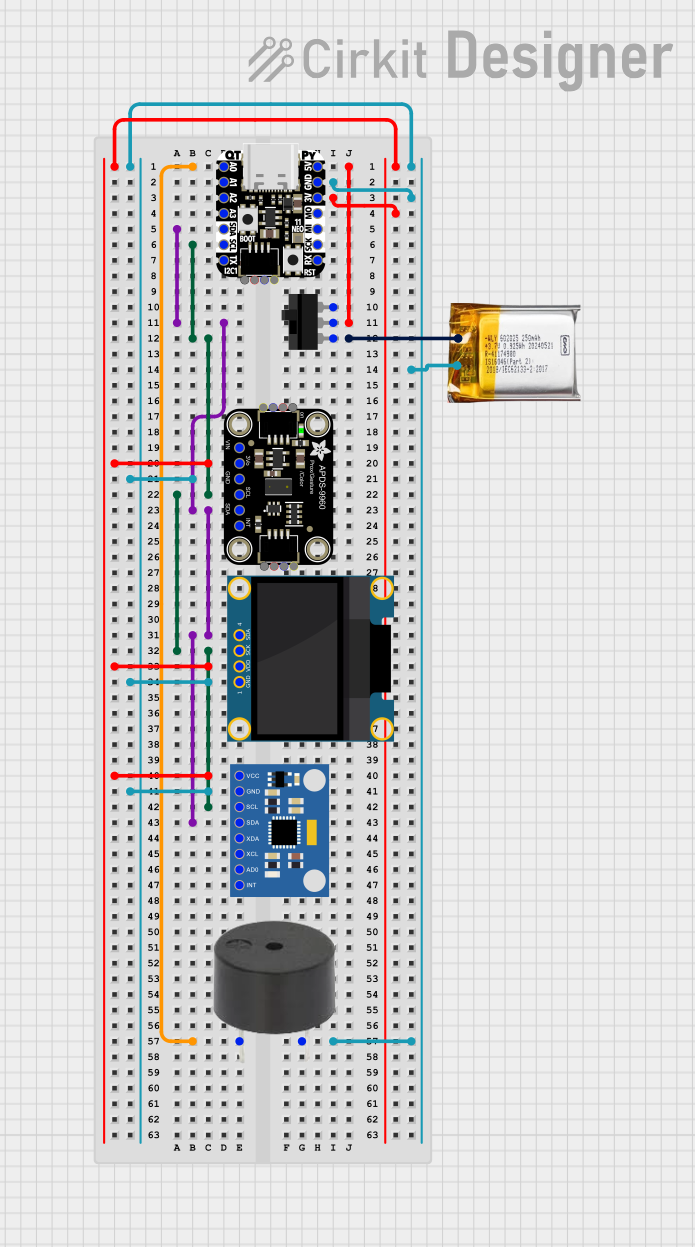
 Open Project in Cirkit Designer
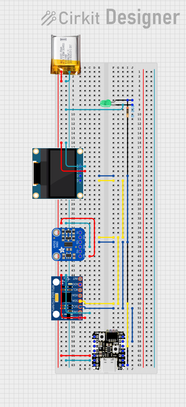
 Open Project in Cirkit Designer
Explore Projects Built with RP2040 Debugger

 Open Project in Cirkit Designer
 Open Project in Cirkit Designer
 Open Project in Cirkit Designer
 Open Project in Cirkit Designer
Common Applications and Use Cases
- Debugging firmware for RP2040-based projects.
- Testing and optimizing embedded applications.
- Educational purposes for learning microcontroller programming and debugging.
- Development of IoT devices, robotics, and other embedded systems.
Technical Specifications
Key Technical Details
- Manufacturer: Raspberry Pi
- Supported Microcontroller: RP2040
- Interface: SWD (Serial Wire Debug)
- Power Supply Voltage: 3.3V (from the target device or external source)
- Communication Protocol: USB for host connection
- Supported Debugging Features:
- Breakpoints
- Step execution
- Variable and memory inspection
- Flash programming
- Operating System Compatibility: Windows, macOS, Linux
- Dimensions: Compact form factor for easy integration into development setups
Pin Configuration and Descriptions
The RP2040 Debugger connects to the RP2040 microcontroller via the SWD interface. Below is the pin configuration:
| Pin Name | Pin Number | Description |
|---|---|---|
| SWDIO | 1 | Serial Wire Debug Input/Output |
| SWCLK | 2 | Serial Wire Debug Clock |
| GND | 3 | Ground |
| 3V3 | 4 | 3.3V Power Supply |
| RESET | 5 | Reset Pin for Target Microcontroller |
Usage Instructions
How to Use the RP2040 Debugger in a Circuit
Connect the Debugger to the RP2040:
- Use the SWDIO, SWCLK, GND, and 3V3 pins to connect the debugger to the RP2040 microcontroller.
- Optionally, connect the RESET pin for additional control over the target device.
Install Required Software:
- Download and install a compatible Integrated Development Environment (IDE) such as Visual Studio Code with the Pico SDK or OpenOCD for debugging.
- Install the necessary drivers for the RP2040 Debugger on your operating system.
Set Up the Debugging Environment:
- Configure the IDE or debugging tool to recognize the RP2040 Debugger.
- Load the firmware or program you wish to debug onto the RP2040 microcontroller.
Start Debugging:
- Use the IDE to set breakpoints, step through code, and inspect variables or memory.
- Monitor the program's behavior and make adjustments as needed.
Important Considerations and Best Practices
- Ensure that the debugger and the RP2040 microcontroller share a common ground (GND).
- Avoid powering the debugger and the target device from separate power sources to prevent ground loops.
- Use short, high-quality wires for SWD connections to minimize signal interference.
- Always verify the pin connections before powering the circuit to avoid damage to the debugger or microcontroller.
Example: Using RP2040 Debugger with Arduino IDE
If you are using the RP2040 microcontroller with the Arduino IDE, you can integrate the debugger as follows:
- Install the Arduino Mbed OS RP2040 core from the Arduino Boards Manager.
- Connect the RP2040 Debugger to the microcontroller as described above.
- Use the following example code to test debugging:
// Example code for debugging with RP2040 Debugger
// This code toggles an LED and can be debugged using breakpoints.

#define LED_PIN 25  // Onboard LED pin for RP2040

void setup() {
  pinMode(LED_PIN, OUTPUT);  // Set LED pin as output
}

void loop() {
  digitalWrite(LED_PIN, HIGH);  // Turn LED on
  delay(1000);                  // Wait for 1 second
  digitalWrite(LED_PIN, LOW);   // Turn LED off
  delay(1000);                  // Wait for 1 second
}
- Set breakpoints in the
loop()function to observe the LED toggling behavior. - Use the debugger to inspect variables and step through the code.
Troubleshooting and FAQs
Common Issues and Solutions
| Issue | Solution |
|---|---|
| Debugger not detected by the IDE | Ensure the debugger is properly connected and the drivers are installed. |
| No response from the target microcontroller | Verify the SWD connections and ensure the microcontroller is powered. |
| Breakpoints not working | Check if the firmware was compiled with debugging symbols enabled. |
| Debugger disconnects frequently | Use shorter, shielded wires to reduce signal interference. |
FAQs
Can the RP2040 Debugger be used with other microcontrollers?
No, the RP2040 Debugger is specifically designed for the RP2040 microcontroller.What software is recommended for debugging?
Visual Studio Code with the Pico SDK or OpenOCD is recommended for debugging RP2040-based projects.Do I need external power for the debugger?
No, the debugger can be powered directly from the target device's 3.3V supply.Can I debug over USB without the SWD interface?
No, the RP2040 Debugger requires the SWD interface for debugging.
By following this documentation, you can effectively use the RP2040 Debugger to streamline your development and debugging process for RP2040-based projects.