How to Use Load Cell Amp: Examples, Pinouts, and Specs
Introduction
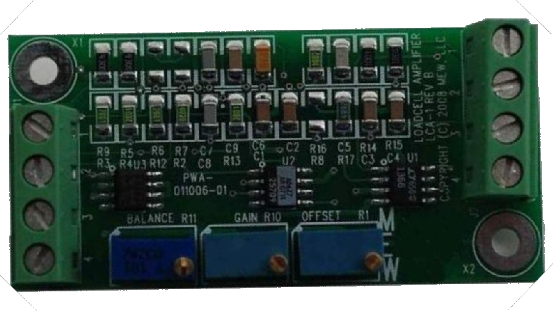
The Load Cell Amplifier (LCA1), manufactured by Moonlite Electro Werks, is a precision electronic device designed to amplify the small electrical signals generated by load cells. Load cells are sensors used to measure weight or force, and their output signals are typically in the millivolt range, which is too weak for direct processing. The LCA1 amplifies these signals to a more usable level, enabling accurate weight or force measurement in various applications.
Explore Projects Built with Load Cell Amp

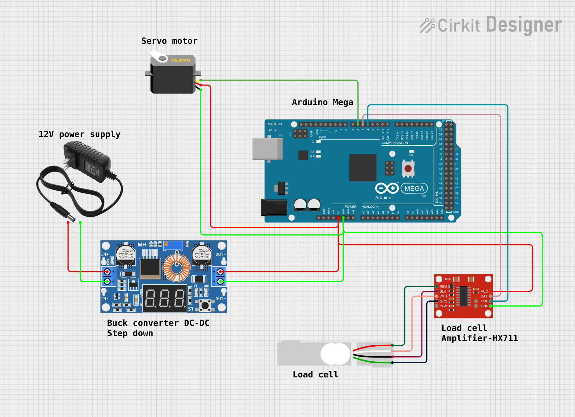

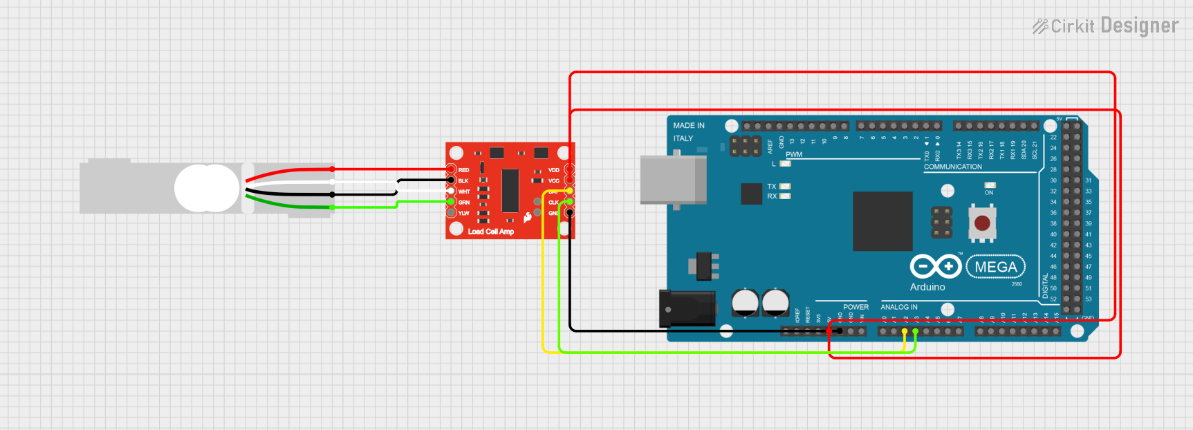
Explore Projects Built with Load Cell Amp
Common Applications and Use Cases
- Weighing Scales: Used in digital scales for industrial, commercial, and personal use.
- Force Measurement: Ideal for applications requiring precise force monitoring, such as material testing.
- Automation Systems: Integrated into automated systems for weight-based sorting or batching.
- IoT Devices: Used in smart systems for weight monitoring and data logging.
- Robotics: For force feedback in robotic arms and grippers.
Technical Specifications
The following table outlines the key technical details of the LCA1 Load Cell Amplifier:
| Parameter | Specification |
|---|---|
| Manufacturer | Moonlite Electro Werks |
| Part ID | LCA1 |
| Input Voltage Range | 3.3V to 5V DC |
| Amplification Gain | Adjustable (up to 128x) |
| Input Signal Range | ±20mV (typical for load cells) |
| Output Signal Range | 0V to 3.3V (analog output) |
| Operating Temperature | -40°C to +85°C |
| Dimensions | 25mm x 20mm x 5mm |
| Interface | Analog output, optional I2C/SPI |
Pin Configuration and Descriptions
The LCA1 features a simple pinout for easy integration into circuits. The table below describes each pin:
| Pin | Name | Description |
|---|---|---|
| 1 | VCC | Power supply input (3.3V to 5V DC). |
| 2 | GND | Ground connection. |
| 3 | IN+ | Positive input from the load cell. |
| 4 | IN- | Negative input from the load cell. |
| 5 | OUT | Amplified analog output signal. |
| 6 | GAIN | Gain adjustment pin (connect to external resistor or potentiometer). |
| 7 | SCL (optional) | I2C clock line (used in digital output mode, if supported). |
| 8 | SDA (optional) | I2C data line (used in digital output mode, if supported). |
Usage Instructions
How to Use the LCA1 in a Circuit
- Power the Amplifier: Connect the VCC pin to a 3.3V or 5V DC power source and the GND pin to ground.
- Connect the Load Cell: Attach the load cell's positive and negative signal wires to the IN+ and IN- pins, respectively.
- Adjust the Gain: Use an external resistor or potentiometer connected to the GAIN pin to set the desired amplification level. Refer to the datasheet for recommended resistor values.
- Read the Output: The amplified signal will be available at the OUT pin. This can be connected to an ADC (Analog-to-Digital Converter) for further processing or directly to a microcontroller.
Important Considerations and Best Practices
- Power Supply: Ensure a stable and noise-free power supply to avoid signal distortion.
- Shielded Cables: Use shielded cables for the load cell connections to minimize interference.
- Calibration: Calibrate the system after installation to ensure accurate measurements.
- Gain Settings: Avoid setting the gain too high, as it may amplify noise along with the signal.
- Temperature Effects: Be aware of temperature variations, as they can affect load cell performance.
Example: Connecting the LCA1 to an Arduino UNO
The LCA1 can be easily interfaced with an Arduino UNO for weight measurement. Below is an example circuit and code:
Circuit Connections
- LCA1 VCC → Arduino 5V
- LCA1 GND → Arduino GND
- LCA1 OUT → Arduino A0 (Analog Input)
- Load Cell IN+ and IN- → Connect to the LCA1 IN+ and IN- pins.
Arduino Code
// Load Cell Amplifier (LCA1) Example Code
// Reads the amplified signal from the LCA1 and displays the value in the Serial Monitor.

const int loadCellPin = A0; // Analog pin connected to LCA1 OUT

void setup() {
  Serial.begin(9600); // Initialize serial communication at 9600 baud
  pinMode(loadCellPin, INPUT); // Set the load cell pin as input
}

void loop() {
  int sensorValue = analogRead(loadCellPin); // Read the analog value from LCA1
  float voltage = (sensorValue / 1023.0) * 5.0; // Convert to voltage (assuming 5V reference)

  // Display the raw value and voltage
  Serial.print("Raw Value: ");
  Serial.print(sensorValue);
  Serial.print(" | Voltage: ");
  Serial.print(voltage, 3); // Display voltage with 3 decimal places
  Serial.println(" V");

  delay(500); // Wait for 500ms before the next reading
}
Troubleshooting and FAQs
Common Issues and Solutions
No Output Signal
- Cause: Incorrect wiring or loose connections.
- Solution: Double-check all connections, especially the load cell and power supply.
Fluctuating Output
- Cause: Electrical noise or unstable power supply.
- Solution: Use a regulated power supply and shielded cables for the load cell.
Output Signal Saturation
- Cause: Gain set too high.
- Solution: Reduce the gain by adjusting the external resistor or potentiometer.
Inaccurate Measurements
- Cause: Load cell not calibrated or temperature effects.
- Solution: Perform a proper calibration and consider using a temperature-compensated load cell.
FAQs
Q1: Can the LCA1 be used with a 3.3V microcontroller?
A1: Yes, the LCA1 supports a 3.3V power supply and outputs a signal within the 0V to 3.3V range, making it compatible with 3.3V microcontrollers.
Q2: How do I adjust the gain?
A2: Connect an external resistor or potentiometer to the GAIN pin. Refer to the datasheet for the resistor value corresponding to the desired gain.
Q3: Can I use the LCA1 with multiple load cells?
A3: No, the LCA1 is designed to work with a single load cell. For multiple load cells, use a summing junction or a dedicated amplifier for each load cell.
Q4: Does the LCA1 support digital output?
A4: Some versions of the LCA1 may support I2C or SPI for digital output. Check the specific model and datasheet for details.