
How to Use seeeduino lorawan: Examples, Pinouts, and Specs
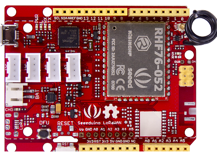
 Design with seeeduino lorawan in Cirkit Designer
Introduction
The Seeeduino LoRaWAN is a microcontroller board tailored for Internet of Things (IoT) applications. It features LoRa (Long Range) communication technology, enabling low-power, long-distance wireless data transmission. This makes it ideal for scenarios where devices need to communicate over extended ranges with minimal power consumption. The board is compatible with the Arduino IDE, simplifying programming and integration with a wide range of sensors and modules.
Explore Projects Built with seeeduino lorawan
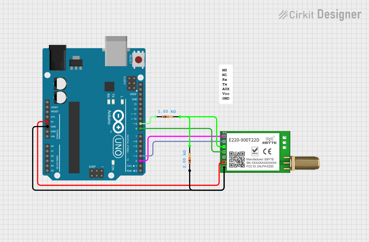 Open Project in Cirkit Designer
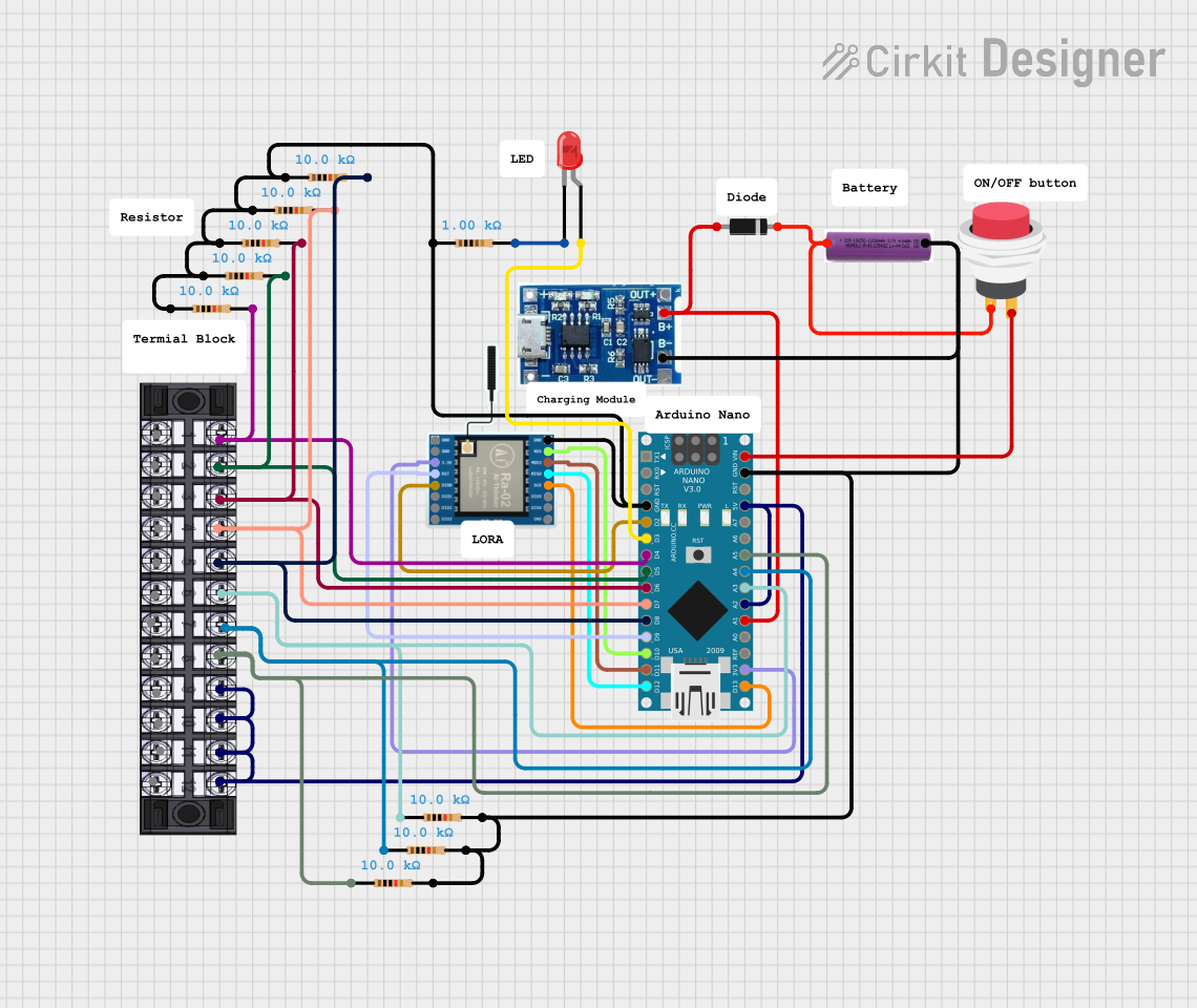 Open Project in Cirkit Designer
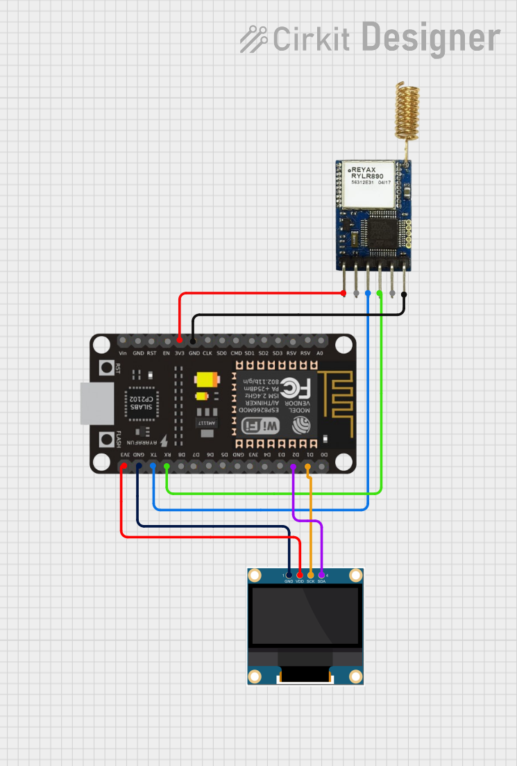 Open Project in Cirkit Designer
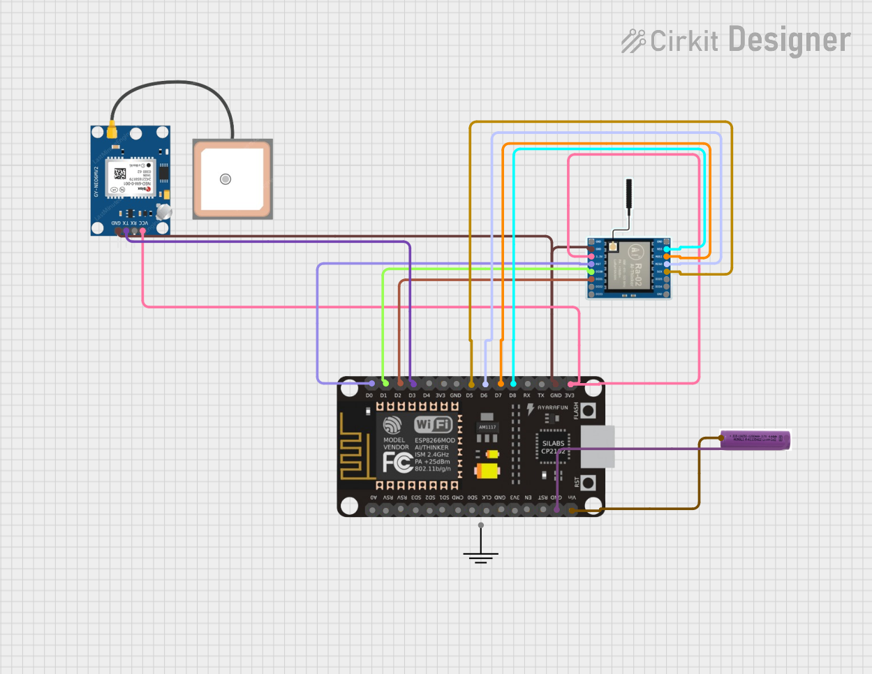 Open Project in Cirkit Designer
Explore Projects Built with seeeduino lorawan
Open Project in Cirkit DesignerOpen Project in Cirkit DesignerOpen Project in Cirkit DesignerOpen Project in Cirkit DesignerCommon Applications and Use Cases
- Smart agriculture (e.g., soil moisture monitoring, weather stations)
- Industrial IoT (e.g., asset tracking, predictive maintenance)
- Smart cities (e.g., parking sensors, environmental monitoring)
- Remote data logging and telemetry
- Home automation and security systems
Technical Specifications
Key Technical Details
| Parameter | Specification |
|---|---|
| Microcontroller | Atmel SAMD21 Cortex-M0+ 32-bit ARM MCU |
| LoRa Module | RHF76-052AM (Semtech SX1276 inside) |
| Frequency Band | 868 MHz (EU) / 915 MHz (US) |
| Communication Protocol | LoRaWAN 1.0.2 |
| Operating Voltage | 3.3V |
| Input Voltage | 5V (via USB) or 3.7V (via LiPo battery) |
| Digital I/O Pins | 14 (12 PWM capable) |
| Analog Input Pins | 6 |
| Flash Memory | 256 KB |
| SRAM | 32 KB |
| Clock Speed | 48 MHz |
| Connectivity | LoRa, UART, I2C, SPI |
| Power Consumption | Ultra-low power (sleep mode supported) |
| Dimensions | 75mm x 25mm |
Pin Configuration and Descriptions
| Pin Name | Description |
|---|---|
| VIN | Input voltage (5V from USB or external power source) |
| 3.3V | Regulated 3.3V output |
| GND | Ground |
| D0 - D13 | Digital I/O pins (PWM capable on D2-D13) |
| A0 - A5 | Analog input pins |
| SDA | I2C data line |
| SCL | I2C clock line |
| RX (D0) | UART receive |
| TX (D1) | UART transmit |
| RST | Reset pin |
| BAT | LiPo battery input (3.7V) |
Usage Instructions
How to Use the Seeeduino LoRaWAN in a Circuit
Powering the Board:
- Connect the board to a computer via a micro-USB cable for programming and power.
- Alternatively, use a 3.7V LiPo battery or an external 5V power source via the VIN pin.
Programming the Board:
- Install the Arduino IDE on your computer.
- Add the Seeeduino LoRaWAN board to the Arduino IDE by navigating to
File > Preferences, and adding the following URL to the "Additional Board Manager URLs":https://files.seeedstudio.com/arduino/package_seeeduino_boards_index.json - Go to
Tools > Board > Boards Manager, search for "Seeeduino LoRaWAN," and install it. - Select the Seeeduino LoRaWAN board and the appropriate COM port under the
Toolsmenu.
Connecting Sensors and Modules:
- Use the digital and analog pins to connect sensors or actuators.
- For I2C devices, connect them to the SDA and SCL pins.
- For SPI devices, use the SPI pins (MISO, MOSI, SCK, and a chip select pin).
LoRa Communication:
- Configure the LoRaWAN settings (e.g., frequency band, device address, network keys) in your code.
- Use the provided LoRaWAN library to send and receive data.
Example Code for LoRa Communication
Below is an example of how to send a simple message using the Seeeduino LoRaWAN:
#include <LoRaWan.h> // Include the LoRaWAN library

void setup() {
  Serial.begin(9600); // Initialize serial communication for debugging
  while (!Serial);

  // Initialize LoRaWAN module
  if (!LoRaWan.begin()) {
    Serial.println("Failed to initialize LoRaWAN module!");
    while (1);
  }

  // Set LoRaWAN parameters (replace with your network details)
  LoRaWan.setDeviceAddress("26011BDA"); // Device address
  LoRaWan.setNetworkSessionKey("2B7E151628AED2A6ABF7158809CF4F3C"); // Network key
  LoRaWan.setAppSessionKey("3B7E151628AED2A6ABF7158809CF4F3C"); // App key

  Serial.println("LoRaWAN initialized successfully!");
}

void loop() {
  // Prepare a message to send
  String message = "Hello, LoRaWAN!";
  Serial.print("Sending message: ");
  Serial.println(message);

  // Send the message
  if (LoRaWan.send(message.c_str(), message.length())) {
    Serial.println("Message sent successfully!");
  } else {
    Serial.println("Failed to send message.");
  }

  delay(10000); // Wait 10 seconds before sending the next message
}
Important Considerations and Best Practices
- Ensure the correct frequency band (868 MHz or 915 MHz) is selected for your region.
- Use a proper antenna to maximize the range and signal quality.
- Avoid placing the board near metal objects or other sources of interference.
- When using a LiPo battery, monitor its charge level to prevent over-discharge.
- Use sleep mode to reduce power consumption in battery-powered applications.
Troubleshooting and FAQs
Common Issues and Solutions
The board is not detected by the Arduino IDE:
- Ensure the correct USB driver is installed.
- Check that the correct COM port is selected in the Arduino IDE.
- Try using a different USB cable or port.
LoRaWAN module fails to initialize:
- Verify that the LoRaWAN library is installed correctly.
- Double-check the device address and network keys in your code.
- Ensure the antenna is securely connected.
Poor signal quality or range:
- Use a high-quality antenna and ensure it is properly connected.
- Avoid obstructions and interference in the signal path.
- Check that the frequency band matches your region's regulations.
The board does not power on:
- Confirm that the power source (USB or battery) is connected and functioning.
- Check for any loose connections or damaged components.
FAQs
Q: Can I use the Seeeduino LoRaWAN with other LoRa devices?
A: Yes, as long as the other devices support the same frequency band and LoRaWAN protocol version.
Q: What is the maximum range of the LoRa communication?
A: The range depends on environmental factors, but it can reach up to 10 km in open areas.
Q: Can I use the board without a LiPo battery?
A: Yes, the board can be powered via USB or an external 5V power source.
Q: Is the Seeeduino LoRaWAN compatible with Arduino libraries?
A: Yes, it is fully compatible with most Arduino libraries and the Arduino IDE.