How to Use DHT11: Examples, Pinouts, and Specs
Introduction
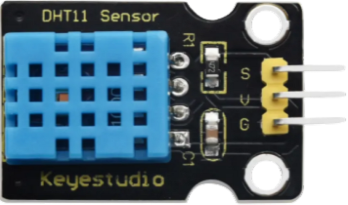
The DHT11 is a digital temperature and humidity sensor manufactured by Keystudio (Part ID: KS0034). It provides accurate readings of temperature in Celsius and relative humidity in percentage. The DHT11 is widely used in applications such as weather stations, HVAC systems, and other projects requiring environmental monitoring. Its compact size, low power consumption, and ease of use make it a popular choice for hobbyists and professionals alike.
Explore Projects Built with DHT11
Explore Projects Built with DHT11
Common Applications
- Weather monitoring systems
- Home automation and HVAC control
- Greenhouse and agricultural monitoring
- IoT (Internet of Things) devices
- Educational projects and prototyping
Technical Specifications
The DHT11 sensor is designed for simplicity and reliability. Below are its key technical details:
| Parameter | Value |
|---|---|
| Operating Voltage | 3.3V to 5.5V |
| Operating Current | 0.3mA (measuring), 60µA (standby) |
| Temperature Range | 0°C to 50°C |
| Temperature Accuracy | ±2°C |
| Humidity Range | 20% to 90% RH |
| Humidity Accuracy | ±5% RH |
| Sampling Period | 1 second |
| Communication Protocol | Single-wire digital signal |
Pin Configuration
The DHT11 sensor typically has 3 or 4 pins, depending on the module version. Below is the pinout description:
3-Pin Module
| Pin | Name | Description |
|---|---|---|
| 1 | VCC | Power supply (3.3V to 5.5V) |
| 2 | DATA | Digital data output (connect to microcontroller) |
| 3 | GND | Ground |
4-Pin Module
| Pin | Name | Description |
|---|---|---|
| 1 | VCC | Power supply (3.3V to 5.5V) |
| 2 | DATA | Digital data output (connect to microcontroller) |
| 3 | NC | Not connected (leave unconnected) |
| 4 | GND | Ground |
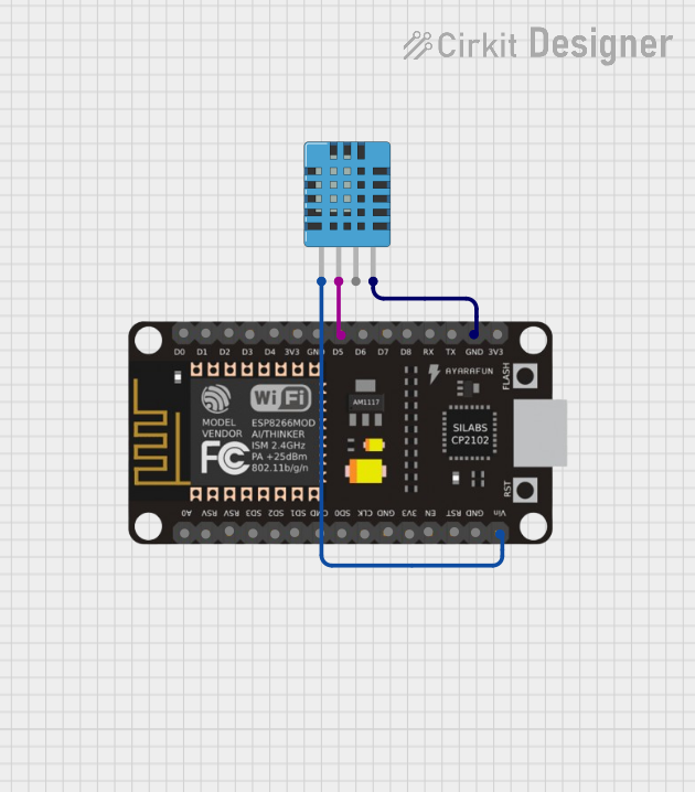
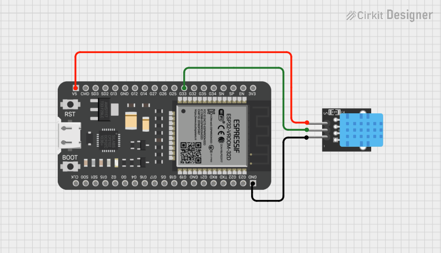
Usage Instructions
The DHT11 sensor is easy to integrate into circuits and works seamlessly with microcontrollers like the Arduino UNO. Below are the steps to use the DHT11 in a circuit:
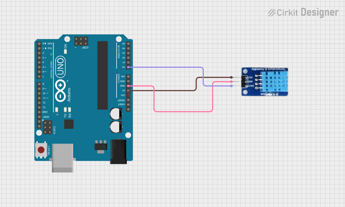
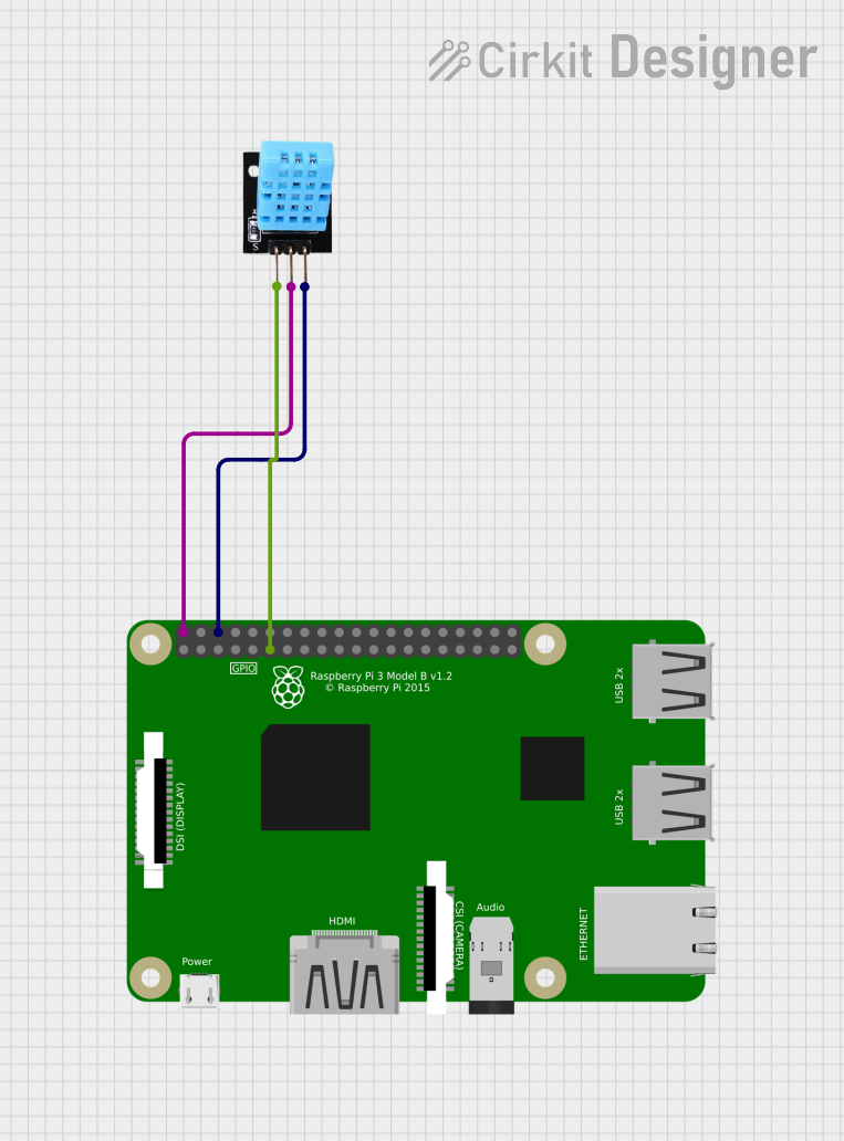
Circuit Connection
- Connect the VCC pin of the DHT11 to the 5V pin of the Arduino UNO.
- Connect the GND pin of the DHT11 to the GND pin of the Arduino UNO.
- Connect the DATA pin of the DHT11 to a digital input pin on the Arduino UNO (e.g., pin 2).
- Use a 10kΩ pull-up resistor between the DATA pin and the VCC pin to ensure stable communication.
Arduino Code Example
Below is an example Arduino sketch to read temperature and humidity data from the DHT11 sensor:
// Include the DHT library for communication with the sensor
#include <DHT.h>

// Define the pin where the DHT11 DATA pin is connected
#define DHTPIN 2

// Define the type of DHT sensor (DHT11 in this case)
#define DHTTYPE DHT11

// Initialize the DHT sensor
DHT dht(DHTPIN, DHTTYPE);

void setup() {
  // Start the serial communication for debugging
  Serial.begin(9600);
  Serial.println("DHT11 Sensor Initialization");

  // Start the DHT sensor
  dht.begin();
}

void loop() {
  // Wait a second between readings (DHT11 has a 1-second sampling period)
  delay(1000);

  // Read temperature in Celsius
  float temperature = dht.readTemperature();
  // Read humidity in percentage
  float humidity = dht.readHumidity();

  // Check if the readings are valid
  if (isnan(temperature) || isnan(humidity)) {
    Serial.println("Failed to read from DHT sensor!");
    return;
  }

  // Print the temperature and humidity values to the Serial Monitor
  Serial.print("Temperature: ");
  Serial.print(temperature);
  Serial.println(" °C");

  Serial.print("Humidity: ");
  Serial.print(humidity);
  Serial.println(" %");
}
Important Considerations
- Ensure the sensor is not exposed to extreme temperatures or humidity levels beyond its specified range.
- Use a pull-up resistor (10kΩ) on the DATA pin to stabilize the signal.
- Allow a 1-second delay between consecutive readings to comply with the DHT11's sampling period.
- Avoid long wires for the DATA pin to prevent signal degradation.
Troubleshooting and FAQs
Common Issues
No Data Output or Incorrect Readings
- Cause: Loose connections or incorrect wiring.
- Solution: Double-check the wiring and ensure the pull-up resistor is connected.
"Failed to read from DHT sensor!" Error
- Cause: Sensor not initialized properly or communication issue.
- Solution: Verify the sensor's power supply and ensure the correct pin is defined in the code.
Inconsistent Readings
- Cause: Electrical noise or long wires.
- Solution: Use shorter wires and ensure proper grounding.
Temperature or Humidity Out of Range
- Cause: Sensor exposed to conditions beyond its operating range.
- Solution: Ensure the sensor is used within its specified temperature and humidity limits.
FAQs
Can the DHT11 measure negative temperatures?
- No, the DHT11 can only measure temperatures in the range of 0°C to 50°C.
What is the maximum cable length for the DHT11?
- The recommended maximum cable length is 20 meters, but this depends on the pull-up resistor value and environmental noise.
Can I use the DHT11 with a 3.3V power supply?
- Yes, the DHT11 operates with a voltage range of 3.3V to 5.5V.
How accurate is the DHT11 compared to other sensors?
- The DHT11 has a temperature accuracy of ±2°C and a humidity accuracy of ±5% RH, which is sufficient for most basic applications. For higher accuracy, consider using the DHT22.
By following this documentation, you can effectively integrate and troubleshoot the DHT11 sensor in your projects.