How to Use Pololu DRV8876 : Examples, Pinouts, and Specs
Introduction
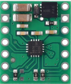
The Pololu DRV8876 is a high-performance motor driver IC designed for driving DC motors and stepper motors. Manufactured by Pololu, this versatile component is built around the DRV8876 QFN chip. It supports a wide operating voltage range of 4.5V to 37V and can deliver up to 3.5A of peak current per channel. The DRV8876 features built-in current sensing, thermal protection, and fault diagnostics, making it a reliable choice for robotics, automation, and other motor control applications.
Explore Projects Built with Pololu DRV8876

Explore Projects Built with Pololu DRV8876
Common Applications
- Robotics and automation systems
- Electric vehicles and drones
- Industrial motor control
- Home automation (e.g., motorized blinds, locks)
- Educational and hobbyist projects
Technical Specifications
Key Technical Details
| Parameter | Value |
|---|---|
| Operating Voltage Range | 4.5V to 37V |
| Continuous Output Current | 2A |
| Peak Output Current | 3.5A |
| Control Interface | PWM or PHASE/ENABLE |
| Current Sensing Accuracy | ±5% |
| Thermal Shutdown | Yes |
| Overcurrent Protection | Yes |
| Package Type | QFN |
Pin Configuration and Descriptions
The DRV8876 QFN package has 16 pins. Below is the pinout and description:
| Pin Number | Pin Name | Description |
|---|---|---|
| 1 | VREF | Reference voltage for current regulation. |
| 2 | IN1 | Input control pin 1 (PWM or PHASE input). |
| 3 | IN2 | Input control pin 2 (ENABLE or PWM input). |
| 4 | nFAULT | Fault output (active low). Indicates fault conditions like overcurrent. |
| 5 | VCC | Logic power supply (3.3V or 5V). |
| 6 | GND | Ground connection. |
| 7 | OUT1 | Motor output 1. |
| 8 | OUT2 | Motor output 2. |
| 9 | ISEN | Current sense output. |
| 10 | VM | Motor power supply (4.5V to 37V). |
| 11-16 | NC | No connection. |
Usage Instructions
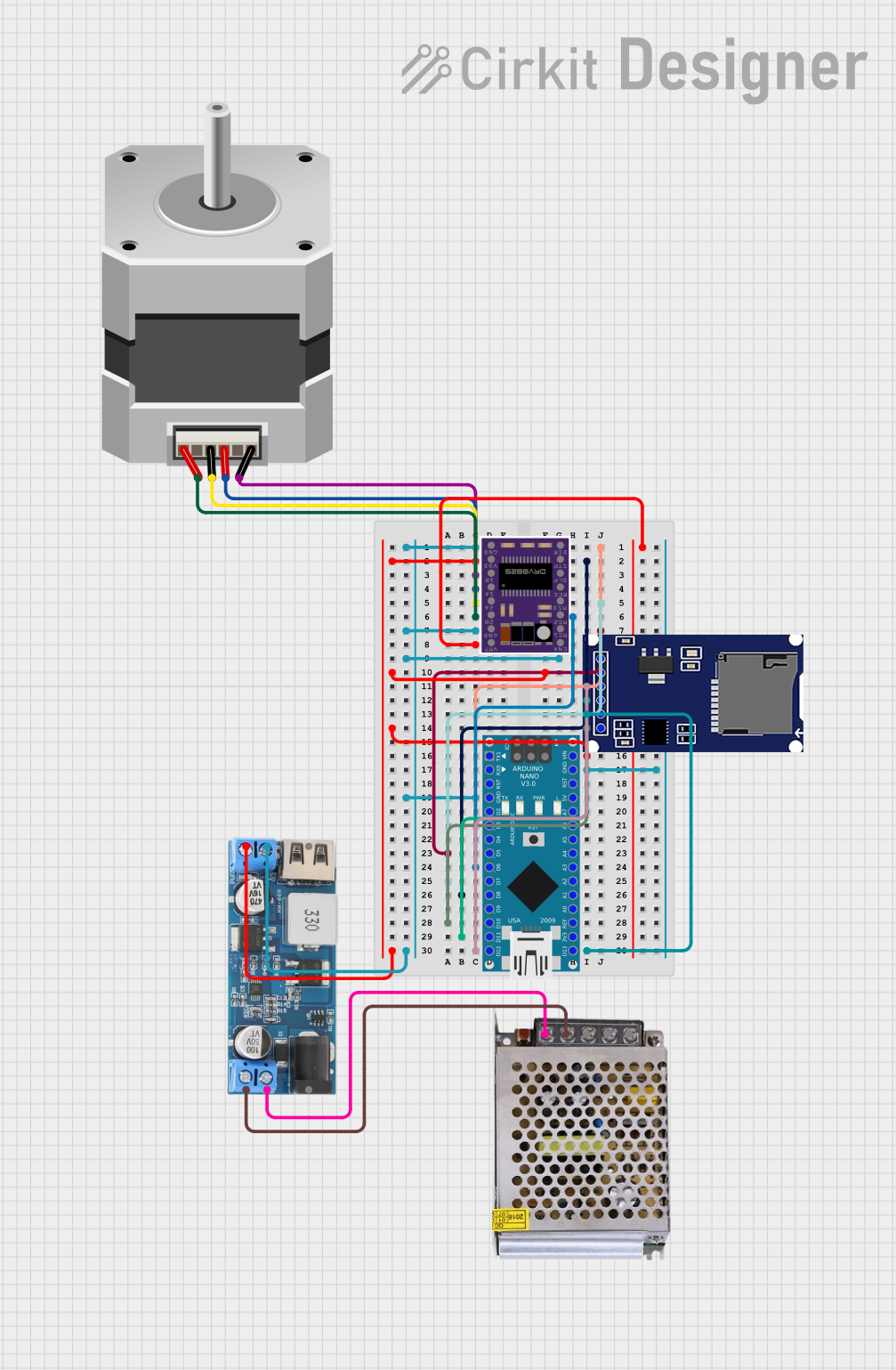
How to Use the DRV8876 in a Circuit
- Power Supply: Connect the motor power supply (VM) to the VM pin. Ensure the voltage is within the 4.5V to 37V range. Connect the logic power supply (3.3V or 5V) to the VCC pin.
- Motor Connections: Connect the motor terminals to the OUT1 and OUT2 pins.
- Control Inputs: Use the IN1 and IN2 pins to control the motor. These pins can be configured for either PWM or PHASE/ENABLE control modes.
- Current Sensing: If current sensing is required, connect the ISEN pin to an ADC input on your microcontroller.
- Fault Monitoring: Connect the nFAULT pin to a digital input on your microcontroller to monitor fault conditions.
Important Considerations
- Heat Dissipation: The DRV8876 can generate heat during operation. Use a heat sink or ensure proper PCB thermal design to prevent overheating.
- Decoupling Capacitors: Place a 0.1µF ceramic capacitor close to the VCC pin and a bulk capacitor (e.g., 100µF) near the VM pin to stabilize the power supply.
- Control Mode Selection: Configure the control mode (PWM or PHASE/ENABLE) based on your application requirements.
Example Code for Arduino UNO
Below is an example of how to control a DC motor using the DRV8876 with an Arduino UNO in PHASE/ENABLE mode:
// Define pin connections
const int phasePin = 9;  // PHASE pin connected to Arduino digital pin 9
const int enablePin = 10; // ENABLE pin connected to Arduino digital pin 10

void setup() {
  // Set control pins as outputs
  pinMode(phasePin, OUTPUT);
  pinMode(enablePin, OUTPUT);
}

void loop() {
  // Rotate motor forward
  digitalWrite(phasePin, HIGH); // Set PHASE to HIGH for forward direction
  analogWrite(enablePin, 128);  // Set ENABLE to 50% duty cycle (speed control)
  delay(2000);                  // Run motor for 2 seconds

  // Rotate motor backward
  digitalWrite(phasePin, LOW);  // Set PHASE to LOW for reverse direction
  analogWrite(enablePin, 128);  // Set ENABLE to 50% duty cycle (speed control)
  delay(2000);                  // Run motor for 2 seconds

  // Stop motor
  analogWrite(enablePin, 0);    // Set ENABLE to 0 (stop motor)
  delay(2000);                  // Wait for 2 seconds
}
Best Practices
- Use appropriate pull-up or pull-down resistors on control pins if required.
- Avoid exceeding the maximum voltage and current ratings to prevent damage.
- Monitor the nFAULT pin to detect and handle fault conditions in your code.
Troubleshooting and FAQs
Common Issues and Solutions
| Issue | Possible Cause | Solution |
|---|---|---|
| Motor does not spin | Incorrect wiring or no power supply | Verify all connections and ensure power is supplied to VM and VCC pins. |
| Motor spins in the wrong direction | Incorrect PHASE pin configuration | Check the PHASE pin logic and adjust as needed. |
| Overheating | Insufficient heat dissipation | Add a heat sink or improve PCB thermal design. |
| nFAULT pin is low | Fault condition (e.g., overcurrent) | Check motor load and ensure it is within the driver's limits. |
FAQs
Can the DRV8876 drive stepper motors? Yes, the DRV8876 can drive stepper motors in full-step or microstepping modes. However, additional control logic is required.
What is the maximum PWM frequency supported? The DRV8876 supports PWM frequencies up to 100 kHz.
Is it possible to use the DRV8876 with a 3.3V microcontroller? Yes, the DRV8876 is compatible with both 3.3V and 5V logic levels.
How do I detect a fault condition? Monitor the nFAULT pin. If it goes low, a fault condition (e.g., overcurrent, thermal shutdown) has occurred. Check the datasheet for fault diagnostics.
By following this documentation, you can effectively integrate the Pololu DRV8876 motor driver into your projects and ensure reliable operation.