
How to Use Adafruit Matrix Portal S3: Examples, Pinouts, and Specs
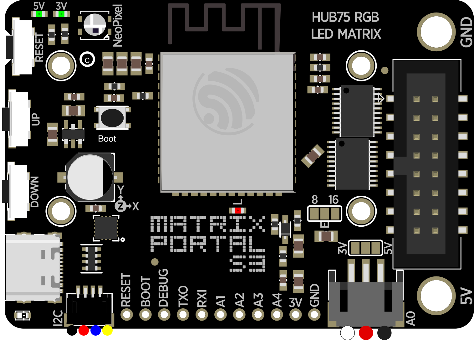
 Design with Adafruit Matrix Portal S3 in Cirkit Designer
Introduction
The Adafruit Matrix Portal S3 (Manufacturer Part ID: 5778) is a versatile microcontroller board designed specifically for driving LED matrices and displays. It features a powerful ESP32-S3 processor with built-in Wi-Fi and Bluetooth connectivity, making it ideal for creating interactive, networked visual projects. The board supports CircuitPython and Arduino, providing flexibility for both beginners and advanced users.
Explore Projects Built with Adafruit Matrix Portal S3
 Open Project in Cirkit Designer
 Open Project in Cirkit Designer
 Open Project in Cirkit Designer
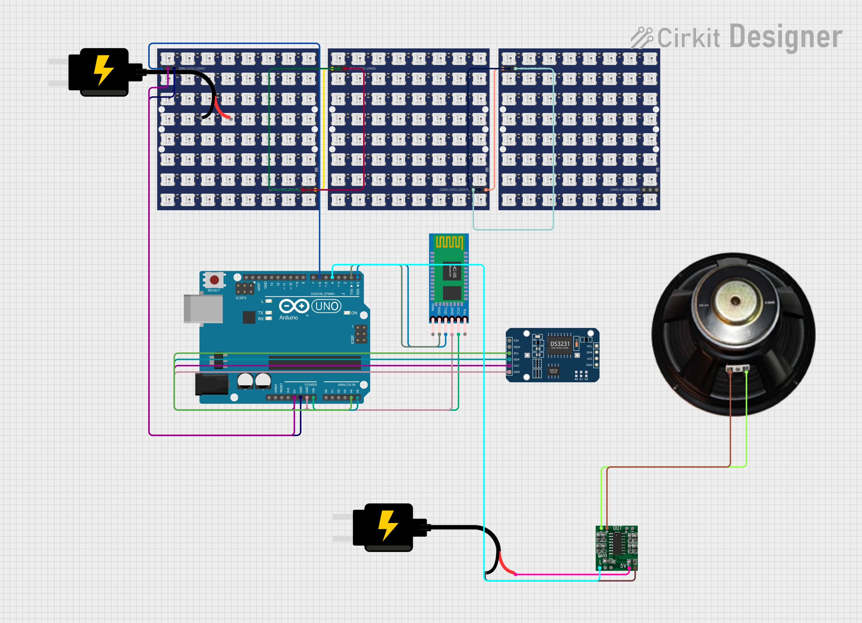 Open Project in Cirkit Designer
Explore Projects Built with Adafruit Matrix Portal S3
Open Project in Cirkit DesignerOpen Project in Cirkit DesignerOpen Project in Cirkit DesignerOpen Project in Cirkit DesignerCommon Applications and Use Cases
- Interactive LED matrix displays
- IoT-enabled visual projects
- Digital signage and message boards
- Animated art installations
- Data visualization and dashboards
- Educational projects for learning programming and electronics
Technical Specifications
Key Technical Details
| Specification | Details |
|---|---|
| Processor | ESP32-S3 dual-core processor with 240 MHz clock speed |
| Flash Memory | 8 MB QSPI Flash |
| RAM | 2 MB PSRAM |
| Connectivity | Wi-Fi (802.11 b/g/n) and Bluetooth 5.0 |
| Power Supply | 5V via USB-C or external power supply |
| USB Interface | USB-C for programming, power, and data transfer |
| LED Matrix Compatibility | HUB75-style RGB LED matrices (up to 64x64 pixels) |
| Programming Support | CircuitPython, Arduino, and ESP-IDF |
| Dimensions | 3.1" x 1.2" (78.7 mm x 30.5 mm) |
Pin Configuration and Descriptions
The Adafruit Matrix Portal S3 features a variety of pins for connecting to LED matrices, sensors, and other peripherals. Below is the pinout description:
| Pin Name | Type | Description |
|---|---|---|
| USB-C | Power/Data | Provides 5V power and data communication for programming and operation. |
| HUB75 Data | Output | Connects to HUB75-style RGB LED matrices for driving displays. |
| GPIO Pins | Input/Output | General-purpose pins for connecting sensors, buttons, or other peripherals. |
| I2C (SDA/SCL) | Communication | I2C interface for connecting compatible devices like sensors or displays. |
| SPI | Communication | SPI interface for high-speed communication with peripherals. |
| 5V/GND | Power | Provides power and ground connections for external devices. |
| Reset Button | Input | Resets the board to restart the program or enter bootloader mode. |
Usage Instructions
How to Use the Component in a Circuit
- Power the Board: Connect the Matrix Portal S3 to a 5V power source using the USB-C port or an external power supply.
- Connect an LED Matrix: Attach a HUB75-compatible RGB LED matrix to the HUB75 connector on the board.
- Program the Board:
- Install CircuitPython or Arduino IDE on your computer.
- Write your code to control the LED matrix or interact with other peripherals.
- Upload the code to the board via the USB-C connection.
- Add Peripherals: Use the GPIO, I2C, or SPI pins to connect additional sensors, buttons, or devices as needed.
Important Considerations and Best Practices
- Ensure the LED matrix is compatible with the HUB75 standard before connecting it to the board.
- Use a sufficient power supply to drive both the Matrix Portal S3 and the connected LED matrix. For larger matrices, an external 5V power source is recommended.
- Avoid shorting pins or connecting incompatible devices to prevent damage to the board.
- Update the firmware regularly to access the latest features and bug fixes.
Example Code for Arduino
Below is an example of how to use the Adafruit Matrix Portal S3 with an LED matrix to display a simple scrolling text message:
#include <Adafruit_GFX.h>       // Core graphics library
#include <RGBmatrixPanel.h>     // Library for HUB75 LED matrices

// Define matrix size (e.g., 32x32 pixels)
#define MATRIX_WIDTH 32
#define MATRIX_HEIGHT 32

// Create an RGB matrix object
RGBmatrixPanel matrix(A, B, C, D, CLK, LAT, OE, false, MATRIX_WIDTH);

void setup() {
  matrix.begin();               // Initialize the matrix
  matrix.setTextWrap(false);    // Disable text wrapping
  matrix.setTextSize(1);        // Set text size
  matrix.setTextColor(matrix.Color333(7, 0, 0)); // Set text color (red)
}

void loop() {
  static int x = MATRIX_WIDTH;  // Start text off-screen
  matrix.fillScreen(0);         // Clear the screen
  matrix.setCursor(x, 0);       // Set text position
  matrix.print("Hello!");       // Display text
  matrix.show();                // Refresh the display
  x--;                          // Move text left
  if (x < -50) x = MATRIX_WIDTH; // Reset position when off-screen
  delay(50);                    // Delay for smooth scrolling
}
Example Code for CircuitPython
Below is an example of how to display a simple message on an LED matrix using CircuitPython:
import board
import displayio
from adafruit_matrixportal.matrix import Matrix
Initialize the matrix
matrix = Matrix(width=64, height=32, bit_depth=6) display = matrix.display
Create a display group
group = displayio.Group()
Create a label to display text
from adafruit_display_text import label from adafruit_bitmap_font import bitmap_font
font = bitmap_font.load_font("/fonts/Arial-16.bdf") # Load a font file text = label.Label(font, text="Hello, World!", color=0xFF0000) # Red text text.x = 10 # X position text.y = 15 # Y position group.append(text)
Show the group on the display
display.show(group)
while True: pass # Keep the program running
Troubleshooting and FAQs
Common Issues and Solutions
LED Matrix Not Displaying Anything:
- Ensure the matrix is properly connected to the HUB75 port.
- Verify that the power supply is sufficient for both the board and the matrix.
- Check your code for errors and ensure it is uploaded correctly.
Wi-Fi or Bluetooth Not Working:
- Confirm that the board's firmware is up to date.
- Double-check your Wi-Fi credentials in the code.
- Ensure the board is within range of the Wi-Fi network.
Board Not Recognized by Computer:
- Use a data-capable USB-C cable (not just a charging cable).
- Try a different USB port or computer.
- Press the reset button to enter bootloader mode.
Flickering or Dim LED Matrix:
- Verify that the power supply can handle the current requirements of the matrix.
- Check for loose connections between the board and the matrix.
FAQs
Can I use this board with other types of LED displays? The Matrix Portal S3 is specifically designed for HUB75-style RGB LED matrices. Other types of displays may require additional hardware or libraries.
What is the maximum size of the LED matrix I can use? The board supports matrices up to 64x64 pixels. Larger matrices may require additional power or processing considerations.
Can I power the board with a battery? Yes, you can use a 5V battery pack with a USB-C output, but ensure it provides sufficient current for both the board and the LED matrix.
Is CircuitPython pre-installed on the board? Yes, the board comes with CircuitPython pre-installed, but you can reflash it with Arduino or other firmware if needed.