
How to Use Netduino Plus: Examples, Pinouts, and Specs
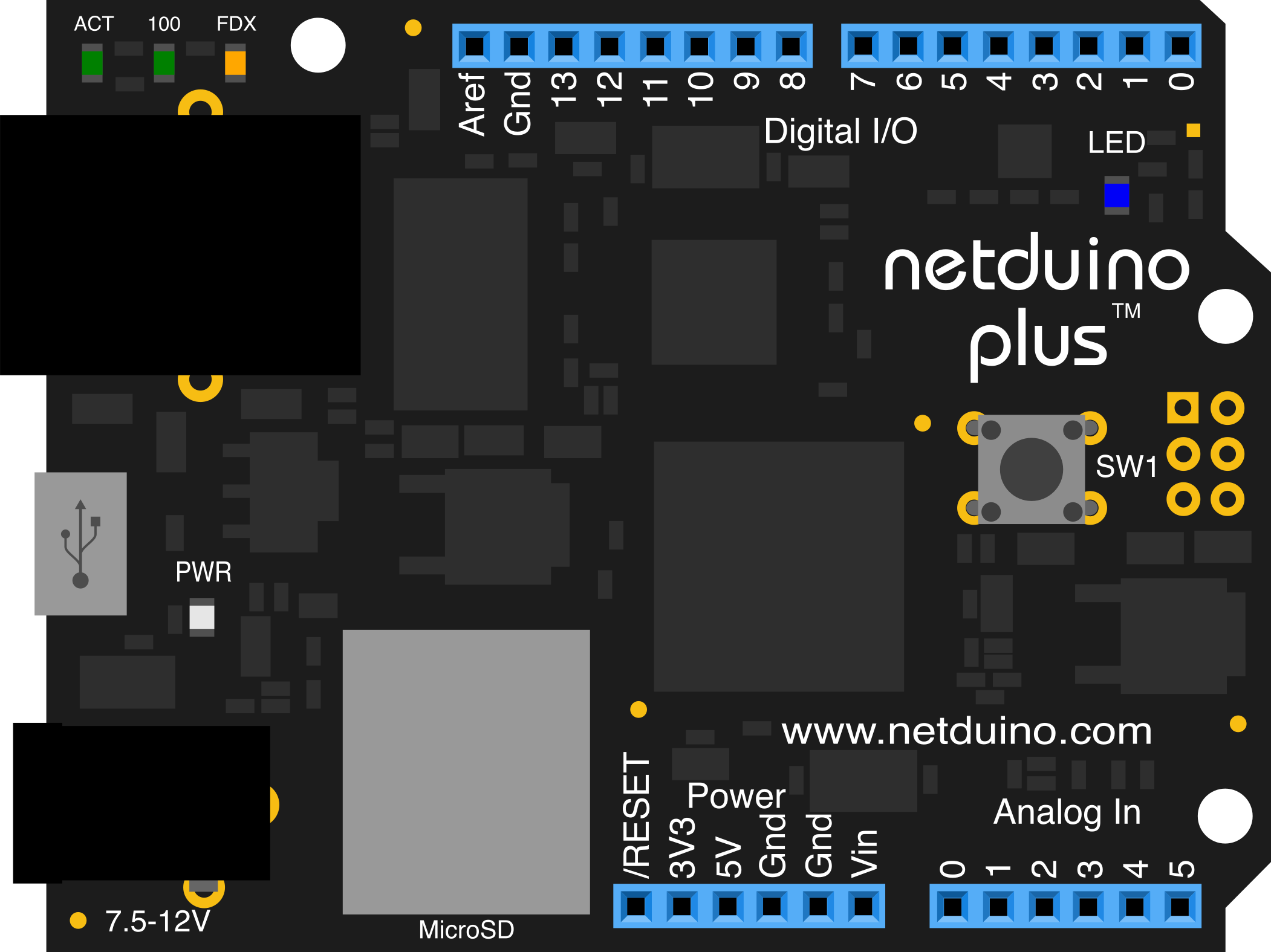
 Design with Netduino Plus in Cirkit Designer
Introduction
The Netduino Plus, manufactured by Secret Labs LLC, is a microcontroller board built on the .NET Micro Framework. It is designed for embedded applications and features an integrated Ethernet port, enabling seamless network connectivity. With its ability to interface with a wide range of sensors and actuators, the Netduino Plus is an excellent choice for Internet of Things (IoT) projects, home automation, and prototyping.
Explore Projects Built with Netduino Plus
 Open Project in Cirkit Designer
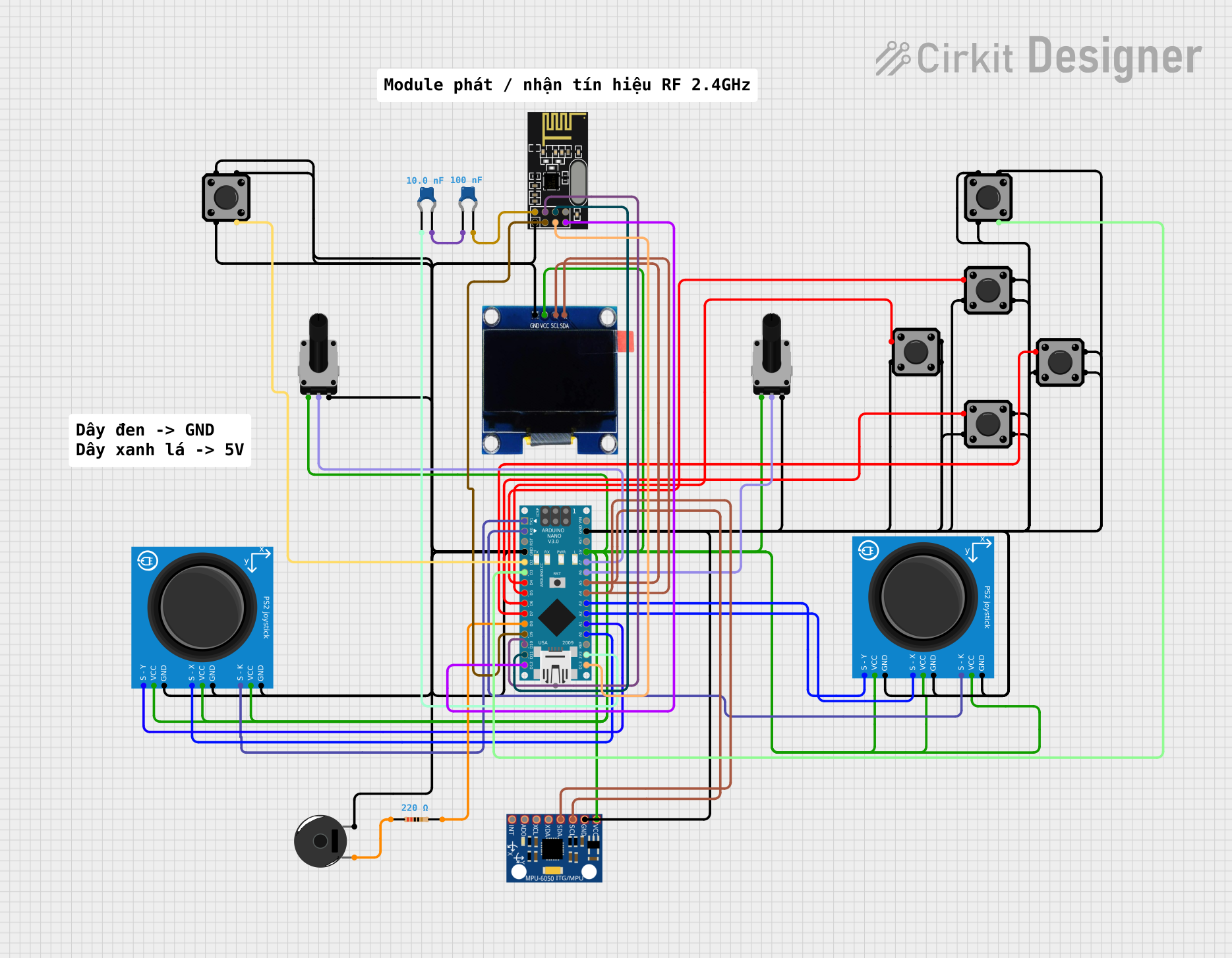 Open Project in Cirkit Designer
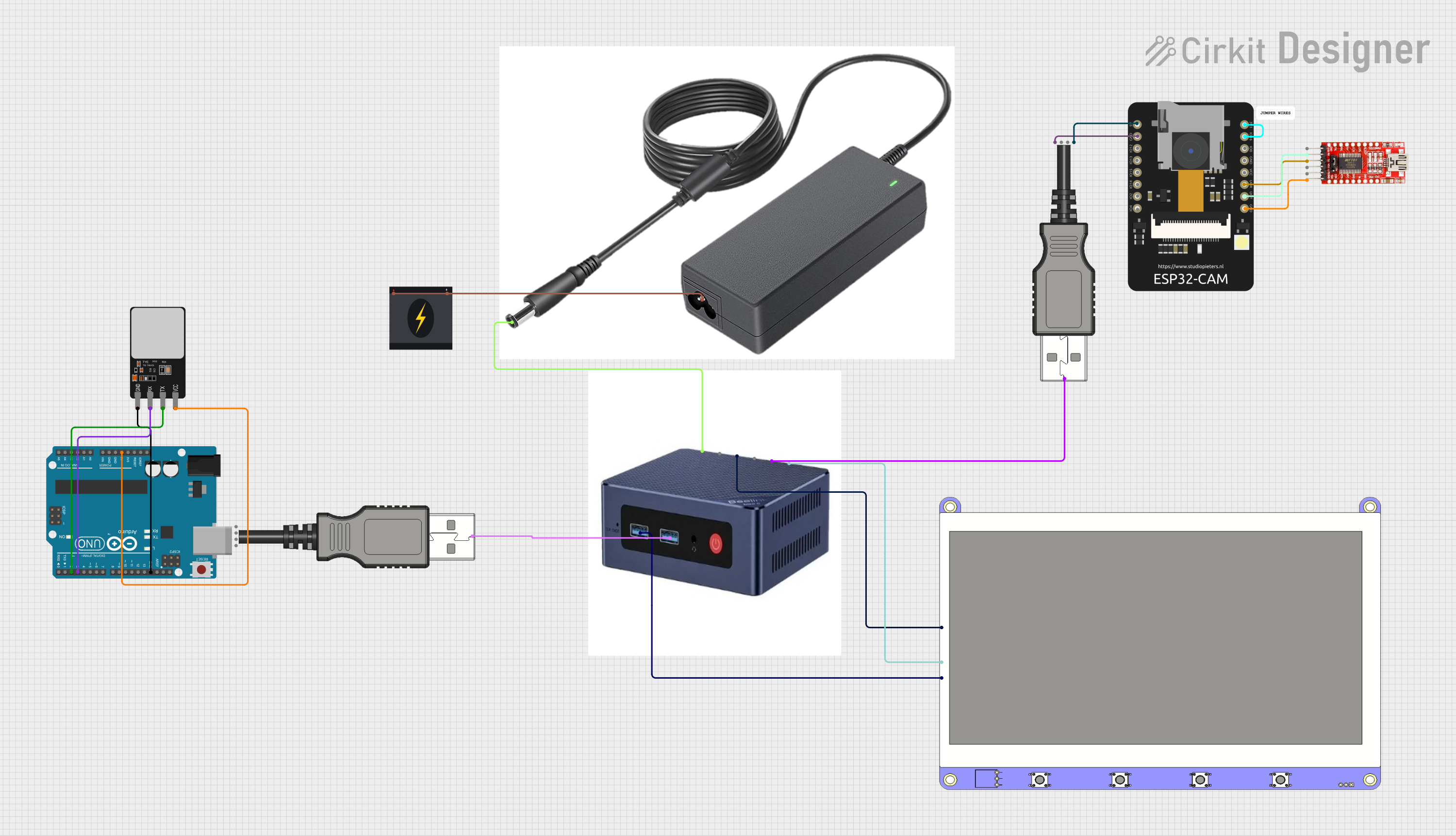 Open Project in Cirkit Designer
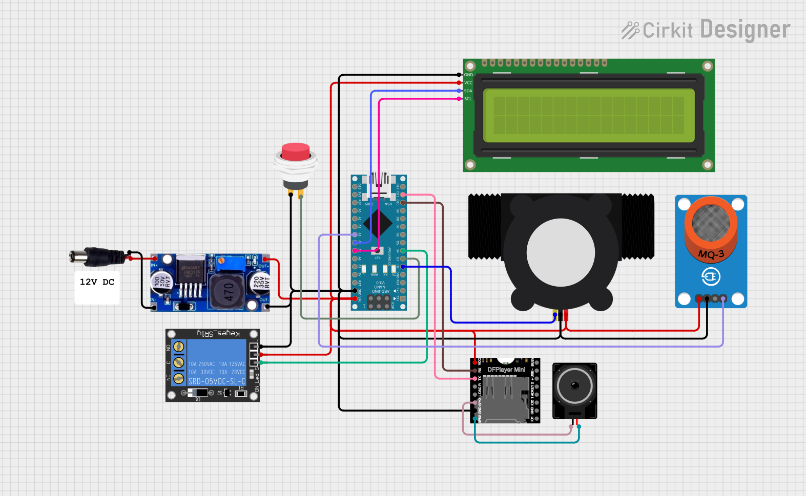 Open Project in Cirkit Designer
Explore Projects Built with Netduino Plus
Open Project in Cirkit DesignerOpen Project in Cirkit DesignerOpen Project in Cirkit DesignerOpen Project in Cirkit DesignerCommon Applications
- IoT devices and smart home systems
- Network-enabled embedded systems
- Data logging and remote monitoring
- Prototyping with .NET-based development tools
Technical Specifications
Key Technical Details
| Specification | Value |
|---|---|
| Microcontroller | Atmel AT91SAM7X512 (ARM7, 32-bit) |
| Clock Speed | 48 MHz |
| Flash Memory | 512 KB |
| RAM | 128 KB |
| Ethernet | 10/100 Mbps Ethernet port |
| Input Voltage (via VIN) | 7-12V |
| Operating Voltage | 3.3V |
| Digital I/O Pins | 20 (of which 6 support PWM) |
| Analog Input Pins | 6 |
| Communication Interfaces | UART, SPI, I2C, Ethernet |
| USB | Full-speed USB 2.0 (for programming/debug) |
| Dimensions | 2.7 x 2.1 inches (68.6 x 53.3 mm) |
Pin Configuration and Descriptions
| Pin Name | Description |
|---|---|
| VIN | Input voltage pin (7-12V) for powering the board. |
| 3.3V | Regulated 3.3V output for powering external components. |
| GND | Ground pins for completing the circuit. |
| Digital Pins 0-19 | General-purpose digital I/O pins. Pins 3, 5, 6, 9, 10, and 11 support PWM. |
| Analog Pins 0-5 | Analog input pins for reading sensor data (10-bit resolution). |
| Ethernet Port | RJ45 connector for network connectivity. |
| USB Port | USB 2.0 port for programming and debugging. |
| Reset Button | Resets the microcontroller. |
Usage Instructions
How to Use the Netduino Plus in a Circuit
Powering the Board:
- Connect a 7-12V DC power supply to the VIN pin or use the USB port for power and programming.
- Ensure the power supply is stable to avoid damaging the board.
Programming the Board:
- Install the .NET Micro Framework SDK and the Netduino SDK on your computer.
- Use Microsoft Visual Studio to write and deploy C# code to the board.
Connecting Sensors and Actuators:
- Use the digital I/O pins for controlling actuators like LEDs, motors, or relays.
- Connect sensors to the analog input pins for reading environmental data.
Using Ethernet:
- Connect the Ethernet port to your network using an RJ45 cable.
- Use the built-in libraries in the .NET Micro Framework to enable network communication.
Important Considerations and Best Practices
- Voltage Levels: The Netduino Plus operates at 3.3V logic levels. Avoid connecting 5V signals directly to the pins to prevent damage.
- Current Limits: Each I/O pin can source/sink a maximum of 8mA. Use external drivers for higher current loads.
- Static Protection: Handle the board with care to avoid electrostatic discharge (ESD) damage.
- Firmware Updates: Ensure the board's firmware is up to date for compatibility with the latest SDKs.
Example Code for Blinking an LED
Here is an example of how to blink an LED connected to digital pin 13:
using System;
using Microsoft.SPOT;
using Microsoft.SPOT.Hardware;
using SecretLabs.NETMF.Hardware;
using SecretLabs.NETMF.Hardware.NetduinoPlus;

public class Program
{
    public static void Main()
    {
        // Initialize digital pin 13 as an output pin
        OutputPort led = new OutputPort(Pins.GPIO_PIN_D13, false);

        while (true)
        {
            led.Write(true);  // Turn the LED on
            System.Threading.Thread.Sleep(500);  // Wait for 500ms

            led.Write(false); // Turn the LED off
            System.Threading.Thread.Sleep(500);  // Wait for 500ms
        }
    }
}
Example Code for Ethernet Communication
Below is an example of setting up a simple web server:
using System;
using System.Net;
using System.Net.Sockets;
using System.Text;
using Microsoft.SPOT;

public class Program
{
    public static void Main()
    {
        // Set up a socket to listen for incoming connections
        Socket server = new Socket(AddressFamily.InterNetwork, SocketType.Stream, ProtocolType.Tcp);
        IPEndPoint endpoint = new IPEndPoint(IPAddress.Any, 80);
        server.Bind(endpoint);
        server.Listen(10);

        Debug.Print("Web server running. Connect to the board's IP address.");

        while (true)
        {
            // Accept incoming connection
            Socket client = server.Accept();
            byte[] buffer = Encoding.UTF8.GetBytes("Hello from Netduino Plus!");
            client.Send(buffer);  // Send response to client
            client.Close();       // Close the connection
        }
    }
}
Troubleshooting and FAQs
Common Issues and Solutions
The board is not detected by the computer:
- Ensure the USB cable is properly connected and functional.
- Check if the correct drivers are installed. Reinstall the Netduino SDK if necessary.
Ethernet connection is not working:
- Verify that the Ethernet cable is securely connected.
- Check the network configuration in your code (e.g., IP address, subnet mask).
- Ensure the router or switch is functioning properly.
Code deployment fails:
- Confirm that the board is in bootloader mode by pressing the reset button.
- Ensure the firmware version matches the SDK version.
Pins are not responding as expected:
- Double-check the wiring and connections.
- Verify that the correct pin numbers are used in the code.
- Ensure the power supply is adequate for the connected components.
FAQs
Q: Can I use 5V sensors with the Netduino Plus?
A: The Netduino Plus operates at 3.3V logic levels. Use a level shifter or voltage divider to interface with 5V sensors.
Q: How do I update the firmware?
A: Download the latest firmware from the Secret Labs website and follow the instructions provided in the documentation.
Q: Can I use the Netduino Plus with Arduino shields?
A: Yes, the Netduino Plus is compatible with most Arduino shields, but ensure the shield operates at 3.3V or includes level shifting.
Q: Is the Netduino Plus suitable for battery-powered projects?
A: Yes, but consider the power consumption of the board and connected peripherals. Use a suitable battery pack and regulator.
By following this documentation, you can effectively utilize the Netduino Plus for your embedded and IoT projects.