Cirkit Designer Logo
Cirkit Designer
Your all-in-one circuit design IDE
Home / 
Component Documentation

How to Use TLV2372: Examples, Pinouts, and Specs

Image of TLV2372
Cirkit Designer LogoDesign with TLV2372 in Cirkit Designer

Introduction

The TLV2372 is a low-power, dual operational amplifier (op-amp) designed for precision signal processing applications. It features a wide supply voltage range, high slew rate, and low quiescent current, making it ideal for battery-powered devices and systems requiring efficient performance. The TLV2372 is well-suited for applications such as sensor signal conditioning, active filters, and low-power analog circuits.

Explore Projects Built with TLV2372

Use Cirkit Designer to design, explore, and prototype these projects online. Some projects support real-time simulation. Click "Open Project" to start designing instantly!
Battery-Powered DC Motor Control with USB Charging and LED Indicator
Image of lumantas: A project utilizing TLV2372 in a practical application
This circuit is designed to charge a Li-ion battery and power a DC motor and a 12V LED. The TP4056 module manages the battery charging process, while the PowerBoost 1000 and MT3608 boost converters step up the voltage to drive the motor and LED, respectively. Two rocker switches control the power flow to the LED and the charging circuit.
Cirkit Designer LogoOpen Project in Cirkit Designer
LD1117 Voltage Regulator Circuit with Input and Output Capacitors
Image of regulator: A project utilizing TLV2372 in a practical application
This circuit is designed to provide a stable output voltage from an input voltage source. It uses an LD1117 voltage regulator in conjunction with an electrolytic capacitor on the input side and a tantalum capacitor on the output side to filter noise and stabilize the voltage. The common ground ensures a reference point for all components.
Cirkit Designer LogoOpen Project in Cirkit Designer
Cellular-Enabled IoT Device with Real-Time Clock and Power Management
Image of LRCM PHASE 2 BASIC: A project utilizing TLV2372 in a practical application
This circuit features a LilyGo-SIM7000G module for cellular communication and GPS functionality, interfaced with an RTC DS3231 for real-time clock capabilities. It includes voltage sensing through two voltage sensor modules, and uses an 8-channel opto-coupler for isolating different parts of the circuit. Power management is handled by a buck converter connected to a DC power source and batteries, with a fuse for protection and a rocker switch for on/off control. Additionally, there's an LED for indication purposes.
Cirkit Designer LogoOpen Project in Cirkit Designer
ESP32-Powered Obstacle Avoidance Robot with IR and Ultrasonic Sensors
Image of projcememek: A project utilizing TLV2372 in a practical application
This circuit features a 18650 Li-Ion battery connected to a TP4056 charging module, which in turn is connected to an MT3608 boost converter to step up the voltage. The output of the MT3608 powers an ESP32 microcontroller, a TCRT 5000 IR sensor, an HC-SR04 ultrasonic sensor, and an MG996R servo motor. The ESP32 is configured to control the servo motor via GPIO 27 and to receive input signals from the IR sensor and ultrasonic sensor through GPIO 14 and GPIO 13, respectively.
Cirkit Designer LogoOpen Project in Cirkit Designer

Explore Projects Built with TLV2372

Use Cirkit Designer to design, explore, and prototype these projects online. Some projects support real-time simulation. Click "Open Project" to start designing instantly!
Image of lumantas: A project utilizing TLV2372 in a practical application
Battery-Powered DC Motor Control with USB Charging and LED Indicator
This circuit is designed to charge a Li-ion battery and power a DC motor and a 12V LED. The TP4056 module manages the battery charging process, while the PowerBoost 1000 and MT3608 boost converters step up the voltage to drive the motor and LED, respectively. Two rocker switches control the power flow to the LED and the charging circuit.
Cirkit Designer LogoOpen Project in Cirkit Designer
Image of regulator: A project utilizing TLV2372 in a practical application
LD1117 Voltage Regulator Circuit with Input and Output Capacitors
This circuit is designed to provide a stable output voltage from an input voltage source. It uses an LD1117 voltage regulator in conjunction with an electrolytic capacitor on the input side and a tantalum capacitor on the output side to filter noise and stabilize the voltage. The common ground ensures a reference point for all components.
Cirkit Designer LogoOpen Project in Cirkit Designer
Image of LRCM PHASE 2 BASIC: A project utilizing TLV2372 in a practical application
Cellular-Enabled IoT Device with Real-Time Clock and Power Management
This circuit features a LilyGo-SIM7000G module for cellular communication and GPS functionality, interfaced with an RTC DS3231 for real-time clock capabilities. It includes voltage sensing through two voltage sensor modules, and uses an 8-channel opto-coupler for isolating different parts of the circuit. Power management is handled by a buck converter connected to a DC power source and batteries, with a fuse for protection and a rocker switch for on/off control. Additionally, there's an LED for indication purposes.
Cirkit Designer LogoOpen Project in Cirkit Designer
Image of projcememek: A project utilizing TLV2372 in a practical application
ESP32-Powered Obstacle Avoidance Robot with IR and Ultrasonic Sensors
This circuit features a 18650 Li-Ion battery connected to a TP4056 charging module, which in turn is connected to an MT3608 boost converter to step up the voltage. The output of the MT3608 powers an ESP32 microcontroller, a TCRT 5000 IR sensor, an HC-SR04 ultrasonic sensor, and an MG996R servo motor. The ESP32 is configured to control the servo motor via GPIO 27 and to receive input signals from the IR sensor and ultrasonic sensor through GPIO 14 and GPIO 13, respectively.
Cirkit Designer LogoOpen Project in Cirkit Designer

Common Applications

  • Sensor signal amplification
  • Active filters (low-pass, high-pass, band-pass)
  • Portable and battery-powered devices
  • Analog-to-digital converter (ADC) buffering
  • Audio signal processing

Technical Specifications

Key Specifications

Parameter Value
Supply Voltage Range 2.7 V to 16 V
Input Offset Voltage 1 mV (typical)
Slew Rate 1.6 V/µs
Gain Bandwidth Product 3 MHz
Quiescent Current (per op-amp) 550 µA (typical)
Output Voltage Swing Rail-to-rail
Operating Temperature Range -40°C to 125°C
Package Options SOIC-8, TSSOP-8

Pin Configuration and Descriptions

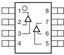
The TLV2372 is available in an 8-pin package. Below is the pinout and description:

Pin Number Pin Name Description
1 OUT1 Output of Op-Amp 1
2 IN1- Inverting Input of Op-Amp 1
3 IN1+ Non-Inverting Input of Op-Amp 1
4 V- (GND) Negative Power Supply or Ground
5 IN2+ Non-Inverting Input of Op-Amp 2
6 IN2- Inverting Input of Op-Amp 2
7 OUT2 Output of Op-Amp 2
8 V+ Positive Power Supply

Usage Instructions

Using the TLV2372 in a Circuit

  1. Power Supply: Connect the V+ pin to a positive voltage source (2.7 V to 16 V) and the V- pin to ground or a negative voltage source, depending on your application.
  2. Input Configuration: Connect the input signals to the IN+ and IN- pins of the desired op-amp. For single-ended input, connect the IN- pin to ground or a reference voltage.
  3. Output: The output signal will be available at the OUT pin of the corresponding op-amp. Ensure the load impedance is within the recommended range to avoid distortion.
  4. Bypass Capacitor: Place a decoupling capacitor (e.g., 0.1 µF) close to the power supply pins to reduce noise and improve stability.

Important Considerations

  • Input Voltage Range: Ensure the input voltage stays within the specified common-mode range to avoid clipping or distortion.
  • Stability: For high-gain configurations, consider adding a small capacitor in parallel with the feedback resistor to improve stability.
  • Thermal Management: Operate the TLV2372 within its specified temperature range to ensure reliable performance.

Example: Connecting TLV2372 to an Arduino UNO

The TLV2372 can be used to amplify an analog signal before feeding it into an Arduino UNO's ADC. Below is an example circuit and code:

Circuit Description

  • Connect the TLV2372's V+ pin to the Arduino's 5V pin and the V- pin to GND.
  • Use Op-Amp 1 to amplify a sensor signal:
    • Connect the sensor output to IN1+.
    • Connect a resistor divider to IN1- for setting a reference voltage.
    • Connect OUT1 to an analog input pin on the Arduino (e.g., A0).

Arduino Code Example

// TLV2372 Example: Reading an amplified sensor signal
const int analogPin = A0; // Analog pin connected to TLV2372 OUT1

void setup() {
  Serial.begin(9600); // Initialize serial communication
}

void loop() {
  int sensorValue = analogRead(analogPin); // Read the amplified signal
  float voltage = sensorValue * (5.0 / 1023.0); // Convert ADC value to voltage
  
  // Print the voltage to the Serial Monitor
  Serial.print("Amplified Signal Voltage: ");
  Serial.println(voltage);
  
  delay(500); // Wait for 500 ms before the next reading
}

Troubleshooting and FAQs

Common Issues

  1. No Output Signal:

    • Verify the power supply connections (V+ and V-).
    • Check the input signal and ensure it is within the common-mode range.
    • Ensure the load impedance is not too low for the op-amp to drive.
  2. Distorted Output:

    • Check if the input signal exceeds the op-amp's input voltage range.
    • Verify that the output is not saturating due to insufficient supply voltage.
  3. Oscillations or Instability:

    • Add a bypass capacitor (0.1 µF) close to the power supply pins.
    • Use proper feedback network design to ensure stability.

FAQs

Q1: Can the TLV2372 operate with a single supply?
A1: Yes, the TLV2372 can operate with a single supply. Connect V- to ground and ensure the input signals are within the common-mode range.

Q2: What is the maximum output current of the TLV2372?
A2: The TLV2372 can source or sink up to 10 mA. Exceeding this limit may damage the device.

Q3: Can the TLV2372 drive capacitive loads?
A3: Yes, but for large capacitive loads, consider adding a series resistor at the output to improve stability.

Q4: Is the TLV2372 suitable for audio applications?
A4: Yes, the TLV2372's low noise and rail-to-rail output make it suitable for low-power audio signal processing.