
How to Use 7 Segment Display - 13mm Common Anode: Examples, Pinouts, and Specs
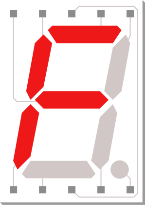
 Design with 7 Segment Display - 13mm Common Anode in Cirkit Designer
Introduction
The 7-segment display is an electronic display device designed to represent decimal numbers and some alphabetic characters. The "13mm" specification refers to the height of each segment, making it suitable for applications requiring clear and visible numeric displays. This particular model is a common anode type, meaning all the anodes of the segments are connected together and must be connected to a positive voltage source. Each segment is illuminated by grounding its respective cathode.
Explore Projects Built with 7 Segment Display - 13mm Common Anode
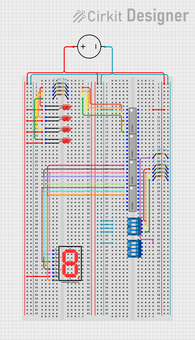 Open Project in Cirkit Designer
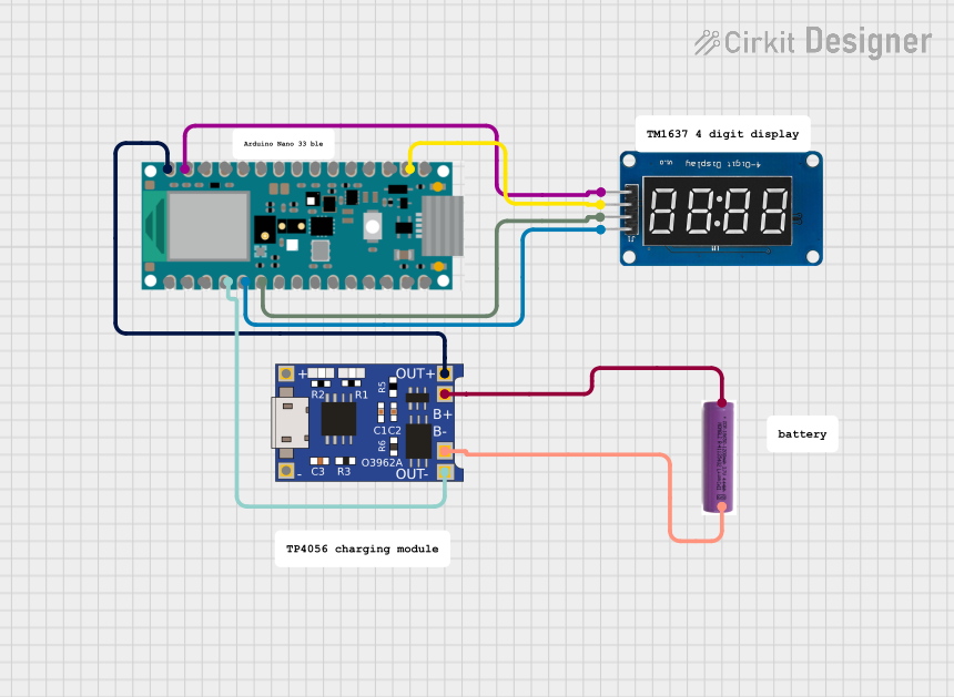 Open Project in Cirkit Designer
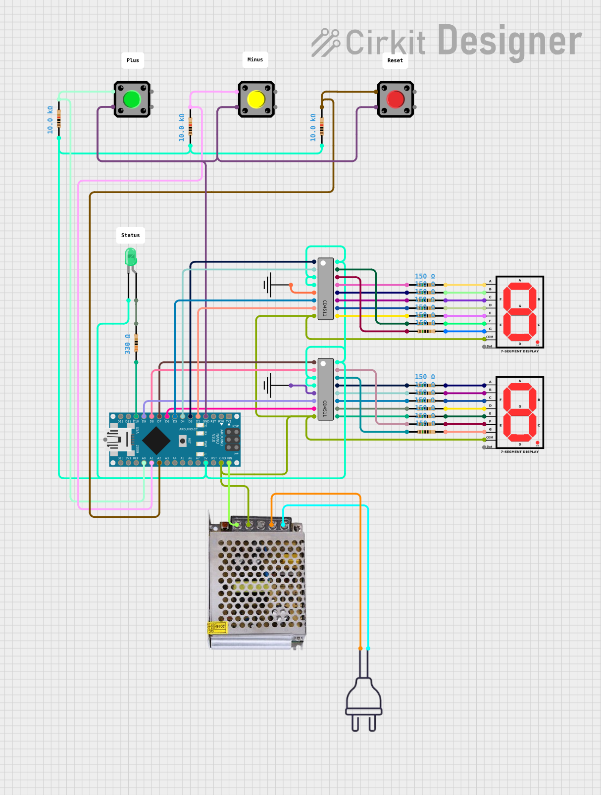 Open Project in Cirkit Designer
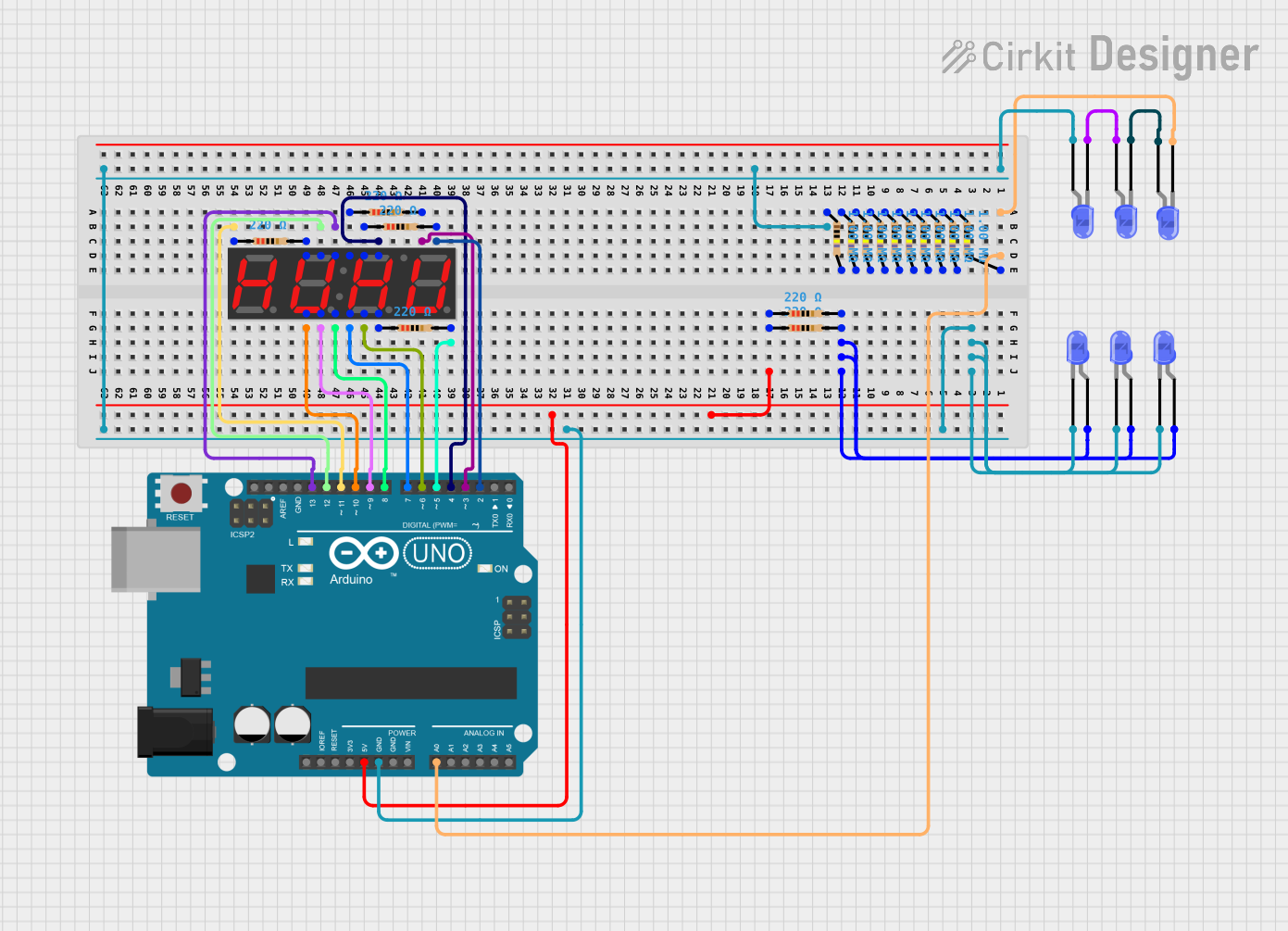 Open Project in Cirkit Designer
Explore Projects Built with 7 Segment Display - 13mm Common Anode
Open Project in Cirkit DesignerOpen Project in Cirkit DesignerOpen Project in Cirkit DesignerOpen Project in Cirkit DesignerCommon Applications
- Digital clocks
- Electronic meters (e.g., voltmeters, ammeters)
- Counters and timers
- Simple numeric displays in embedded systems
Technical Specifications
Below are the key technical details for the 7 Segment Display - 13mm Common Anode:
| Parameter | Value |
|---|---|
| Display Type | 7-segment, Common Anode |
| Segment Height | 13mm |
| Operating Voltage | 2V (per segment, typical) |
| Forward Current (If) | 20mA (per segment, typical) |
| Peak Forward Current | 100mA (per segment, max) |
| Reverse Voltage (Vr) | 5V (max) |
| Operating Temperature | -40°C to +85°C |
| Number of Pins | 10 |
Pin Configuration
The 7-segment display has 10 pins, as shown in the table below. Each pin corresponds to a specific segment or the common anode.
| Pin Number | Connection | Description |
|---|---|---|
| 1 | E | Controls segment "E" |
| 2 | D | Controls segment "D" |
| 3 | Common Anode | Connect to positive voltage (Vcc) |
| 4 | C | Controls segment "C" |
| 5 | Decimal Point | Controls the decimal point (DP) |
| 6 | B | Controls segment "B" |
| 7 | A | Controls segment "A" |
| 8 | Common Anode | Connect to positive voltage (Vcc) |
| 9 | F | Controls segment "F" |
| 10 | G | Controls segment "G" |
Usage Instructions
Connecting the 7-Segment Display
- Power Supply: Connect one of the common anode pins (Pin 3 or Pin 8) to the positive voltage supply (Vcc). Typically, 5V is used in most circuits.
- Resistors: Use current-limiting resistors (220Ω to 1kΩ) between each segment pin and the microcontroller or driver circuit to prevent excessive current flow.
- Segment Control: Connect the cathode pins (A, B, C, D, E, F, G, and DP) to the microcontroller or driver circuit. Set the corresponding pin LOW to illuminate the segment.
Example Circuit with Arduino UNO
Below is an example of how to connect and control the 7-segment display using an Arduino UNO:
Circuit Connections
- Connect Pin 3 (Common Anode) to the 5V pin on the Arduino.
- Connect Pins 1, 2, 4, 5, 6, 7, 9, and 10 to digital pins on the Arduino via 220Ω resistors.
- Use the following pin mapping for the Arduino:
- A → Pin 2
- B → Pin 3
- C → Pin 4
- D → Pin 5
- E → Pin 6
- F → Pin 7
- G → Pin 8
- DP → Pin 9 (optional)
Arduino Code Example
// Define Arduino pins connected to the 7-segment display
const int segmentPins[] = {2, 3, 4, 5, 6, 7, 8, 9};
// Order: A, B, C, D, E, F, G, DP

// Segment patterns for digits 0-9 (Common Anode)
// 1 = OFF, 0 = ON
const byte digitPatterns[10] = {
  0b11000000, // 0
  0b11111001, // 1
  0b10100100, // 2
  0b10110000, // 3
  0b10011001, // 4
  0b10010010, // 5
  0b10000010, // 6
  0b11111000, // 7
  0b10000000, // 8
  0b10010000  // 9
};

void setup() {
  // Set all segment pins as OUTPUT
  for (int i = 0; i < 8; i++) {
    pinMode(segmentPins[i], OUTPUT);
  }
}

void loop() {
  // Display digits 0-9 with a 1-second delay
  for (int digit = 0; digit < 10; digit++) {
    displayDigit(digit);
    delay(1000); // Wait for 1 second
  }
}

// Function to display a digit on the 7-segment display
void displayDigit(int digit) {
  byte pattern = digitPatterns[digit];
  for (int i = 0; i < 8; i++) {
    // Write HIGH or LOW to each segment pin based on the pattern
    digitalWrite(segmentPins[i], bitRead(pattern, i));
  }
}
Best Practices
- Always use current-limiting resistors to protect the segments from overcurrent.
- Avoid exceeding the maximum forward current (20mA per segment) to ensure longevity.
- If using multiple displays, consider using a driver IC (e.g., MAX7219) for easier control.
Troubleshooting and FAQs
Common Issues
Segments Not Lighting Up
- Cause: Incorrect wiring or missing current-limiting resistors.
- Solution: Double-check the connections and ensure resistors are in place.
Dim or Uneven Brightness
- Cause: Resistors with incorrect values or insufficient power supply.
- Solution: Use resistors in the range of 220Ω to 1kΩ and ensure the power supply can handle the current demand.
Incorrect Digits Displayed
- Cause: Incorrect segment-to-pin mapping in the code.
- Solution: Verify the pin mapping in the code matches the physical connections.
Overheating
- Cause: Excessive current through the segments.
- Solution: Use appropriate resistors and avoid exceeding the maximum current rating.
FAQs
Q: Can I use this display with a 3.3V microcontroller?
A: Yes, but ensure the forward voltage of the segments is compatible. You may need to adjust resistor values accordingly.
Q: How do I control multiple 7-segment displays?
A: Use a driver IC like the MAX7219 or multiplexing techniques to control multiple displays efficiently.
Q: Can I display letters on this 7-segment display?
A: Yes, but only a limited set of letters (e.g., A, b, C, d, E, F) can be represented due to the segment layout.
By following this documentation, you can effectively integrate and troubleshoot the 7 Segment Display - 13mm Common Anode in your projects!