How to Use M5_ADS1100: Examples, Pinouts, and Specs
Introduction
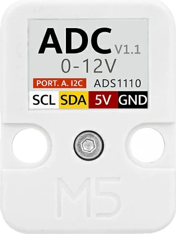
The M5_ADS1100 is a high-precision, 16-bit analog-to-digital converter (ADC) that communicates via the I2C protocol. It is designed for low-power applications, making it an excellent choice for battery-powered devices. The M5_ADS1100 is capable of converting analog signals into precise digital values, which makes it ideal for interfacing with sensors and other analog devices.
Explore Projects Built with M5_ADS1100
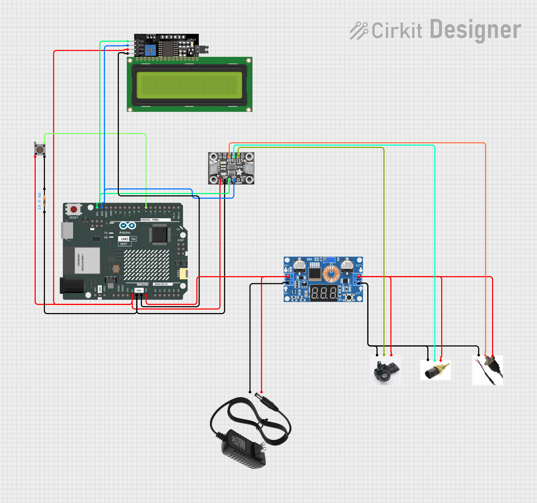

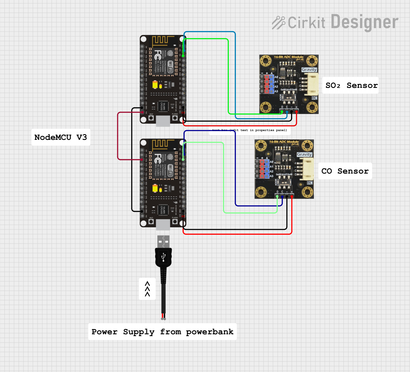

Explore Projects Built with M5_ADS1100
Common Applications and Use Cases
- Sensor data acquisition (e.g., temperature, pressure, light sensors)
- Battery monitoring systems
- Portable medical devices
- Industrial process control
- Data logging systems
Technical Specifications
The M5_ADS1100 offers the following key technical features:
| Parameter | Value |
|---|---|
| Resolution | 16-bit |
| Input Voltage Range | 0V to VDD |
| Supply Voltage (VDD) | 2.7V to 5.5V |
| Power Consumption | 90 µA (typical) |
| I2C Address | Configurable (default: 0x48) |
| Data Rate | 8 SPS to 128 SPS |
| Operating Temperature | -40°C to +125°C |
| Communication Protocol | I2C |
Pin Configuration and Descriptions
The M5_ADS1100 is typically available in an 8-pin package. Below is the pinout and description:
| Pin | Name | Description |
|---|---|---|
| 1 | VDD | Power supply (2.7V to 5.5V) |
| 2 | GND | Ground |
| 3 | SCL | I2C clock line |
| 4 | SDA | I2C data line |
| 5 | A0 | Address selection bit 0 |
| 6 | A1 | Address selection bit 1 |
| 7 | NC | No connection (leave unconnected) |
| 8 | NC | No connection (leave unconnected) |
Usage Instructions
How to Use the M5_ADS1100 in a Circuit
- Power Supply: Connect the VDD pin to a stable power source (2.7V to 5.5V) and the GND pin to ground.
- I2C Communication: Connect the SCL and SDA pins to the corresponding I2C lines of your microcontroller. Use pull-up resistors (typically 4.7kΩ) on both lines.
- Address Configuration: Use the A0 and A1 pins to set the I2C address. These pins can be connected to VDD or GND to configure the address.
- Analog Input: Connect the analog signal to be measured to the input pin of the ADC (refer to the datasheet for specific input pin details).
Important Considerations and Best Practices
- Input Voltage Range: Ensure the input signal does not exceed the supply voltage (VDD). Use a voltage divider or buffer circuit if necessary.
- I2C Pull-Up Resistors: Always include pull-up resistors on the SCL and SDA lines to ensure proper I2C communication.
- Bypass Capacitor: Place a 0.1µF ceramic capacitor close to the VDD pin to filter out noise.
- Data Rate: Choose an appropriate data rate (8 SPS to 128 SPS) based on your application's requirements for speed and resolution.
Example Code for Arduino UNO
Below is an example of how to interface the M5_ADS1100 with an Arduino UNO using the Wire library:
#include <Wire.h>

#define ADS1100_ADDRESS 0x48  // Default I2C address of the M5_ADS1100

void setup() {
  Wire.begin();  // Initialize I2C communication
  Serial.begin(9600);  // Initialize serial communication for debugging

  // Configure the ADS1100 (e.g., set data rate and gain)
  Wire.beginTransmission(ADS1100_ADDRESS);
  Wire.write(0x8C);  // Configuration byte: 16-bit, 128 SPS, gain = 1
  Wire.endTransmission();
}

void loop() {
  int16_t adcValue = readADS1100();  // Read ADC value
  float voltage = (adcValue * 5.0) / 32768.0;  // Convert to voltage (assuming VDD = 5V)

  Serial.print("ADC Value: ");
  Serial.print(adcValue);
  Serial.print(" | Voltage: ");
  Serial.println(voltage, 3);  // Print voltage with 3 decimal places

  delay(1000);  // Wait 1 second before the next reading
}

int16_t readADS1100() {
  Wire.requestFrom(ADS1100_ADDRESS, 2);  // Request 2 bytes from the ADC
  while (Wire.available() < 2);  // Wait for data to be available

  uint8_t msb = Wire.read();  // Most significant byte
  uint8_t lsb = Wire.read();  // Least significant byte

  // Combine the two bytes into a 16-bit value
  return (int16_t)((msb << 8) | lsb);
}
Troubleshooting and FAQs
Common Issues and Solutions
No I2C Communication:
- Ensure the SCL and SDA lines have proper pull-up resistors (4.7kΩ recommended).
- Verify the I2C address matches the configuration of the A0 and A1 pins.
- Check the wiring for loose or incorrect connections.
Incorrect ADC Readings:
- Ensure the input voltage is within the specified range (0V to VDD).
- Verify the configuration byte sent to the ADS1100 matches your desired settings.
- Check for noise or interference on the analog input signal.
Device Not Detected:
- Use an I2C scanner sketch to confirm the device's address.
- Ensure the power supply voltage is within the specified range (2.7V to 5.5V).
FAQs
Q: Can the M5_ADS1100 measure negative voltages?
A: No, the M5_ADS1100 can only measure voltages in the range of 0V to VDD. For differential measurements, refer to the datasheet for specific configurations.
Q: What is the maximum sampling rate of the M5_ADS1100?
A: The maximum sampling rate is 128 samples per second (SPS).
Q: Do I need an external clock for the M5_ADS1100?
A: No, the M5_ADS1100 has an internal clock and does not require an external clock source.