How to Use SPDT Relay Module: Examples, Pinouts, and Specs
Introduction
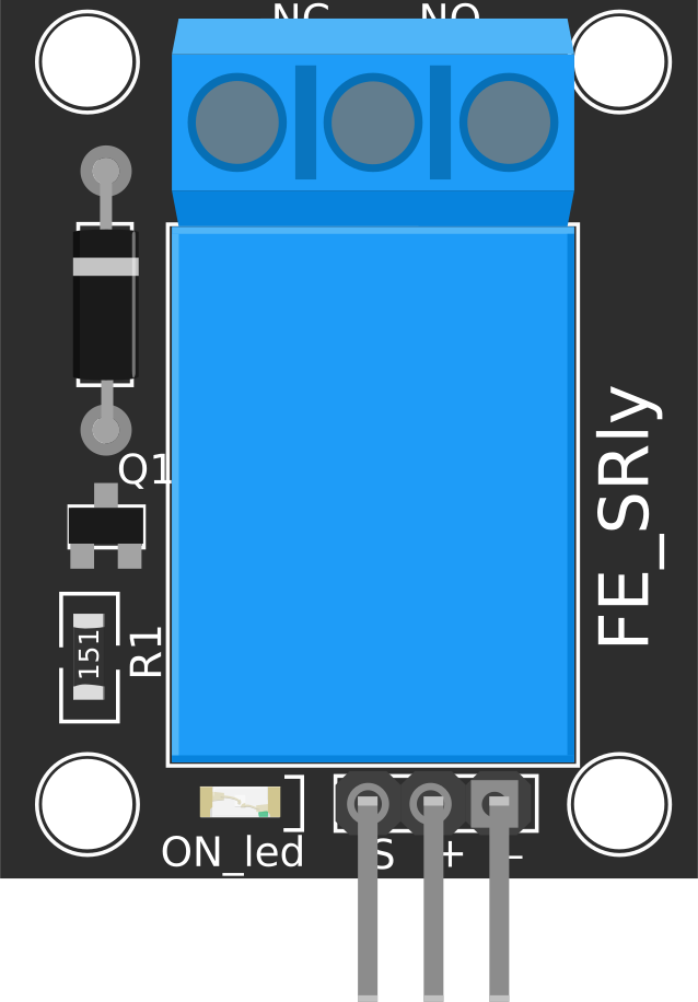
The Single Pole Double Throw (SPDT) relay module is an electromechanical switch designed to control circuits using either low-power or high-power signals. It features three terminals: Common (COM), Normally Open (NO), and Normally Closed (NC). This configuration allows the relay to switch between two circuits, making it a versatile component for various applications.
Explore Projects Built with SPDT Relay Module


Explore Projects Built with SPDT Relay Module
Common Applications and Use Cases
- Home Automation: Controlling lights, fans, or appliances remotely.
- Industrial Automation: Switching high-power devices using low-power control signals.
- Microcontroller Projects: Interfacing with Arduino, Raspberry Pi, or other microcontrollers.
- Motor Control: Switching between forward and reverse motor directions.
- Safety Systems: Isolating circuits to prevent damage or hazards.
Technical Specifications
Key Technical Details
- Operating Voltage: 5V DC (common for most modules, but check your specific model)
- Trigger Voltage: Typically 3.3V to 5V (compatible with microcontrollers like Arduino)
- Maximum Switching Voltage: 250V AC or 30V DC (varies by model)
- Maximum Switching Current: 10A (varies by model)
- Relay Type: SPDT (Single Pole Double Throw)
- Isolation: Optocoupler isolation (on some modules) for safe operation
- Indicator LED: Built-in LED to indicate relay activation
Pin Configuration and Descriptions
The SPDT relay module typically has the following pins:
| Pin Name | Description |
|---|---|
| VCC | Power supply pin (5V DC) |
| GND | Ground connection |
| IN | Control signal input (activates the relay when HIGH) |
| COM | Common terminal for the load circuit |
| NO | Normally Open terminal (connected to COM when the relay is activated) |
| NC | Normally Closed terminal (connected to COM when the relay is not activated) |
Usage Instructions
How to Use the SPDT Relay Module in a Circuit
- Power the Module: Connect the VCC pin to a 5V DC power source and the GND pin to ground.
- Control Signal: Connect the IN pin to a digital output pin of a microcontroller (e.g., Arduino).
- Load Connection:
- Connect the load's power source to the COM terminal.
- Connect the load to either the NO or NC terminal, depending on the desired behavior:
- NO: The load is powered only when the relay is activated.
- NC: The load is powered when the relay is not activated.
- Activate the Relay: Send a HIGH signal (e.g., 5V) to the IN pin to activate the relay and switch the load.
Important Considerations and Best Practices
- Isolation: Ensure proper isolation between the control circuit and the high-power load to prevent damage.
- Flyback Diode: If controlling an inductive load (e.g., motor), use a flyback diode across the load to protect the relay from voltage spikes.
- Power Ratings: Do not exceed the relay's voltage and current ratings to avoid overheating or damage.
- Indicator LED: Use the built-in LED to verify relay activation during testing.
Example: Connecting to an Arduino UNO
Below is an example of how to control an SPDT relay module using an Arduino UNO:
// Define the relay control pin
const int relayPin = 7; // Connect the IN pin of the relay module to pin 7

void setup() {
  pinMode(relayPin, OUTPUT); // Set the relay pin as an output
  digitalWrite(relayPin, LOW); // Ensure the relay is off at startup
}

void loop() {
  // Turn the relay ON
  digitalWrite(relayPin, HIGH); // Send a HIGH signal to activate the relay
  delay(5000); // Keep the relay ON for 5 seconds

  // Turn the relay OFF
  digitalWrite(relayPin, LOW); // Send a LOW signal to deactivate the relay
  delay(5000); // Keep the relay OFF for 5 seconds
}
Troubleshooting and FAQs
Common Issues and Solutions
Relay Not Activating:
- Cause: Insufficient control signal voltage.
- Solution: Ensure the IN pin receives a HIGH signal (3.3V or 5V, depending on the module).
Load Not Switching:
- Cause: Incorrect wiring of the load to the COM, NO, or NC terminals.
- Solution: Double-check the load connections and ensure they match the desired behavior (NO or NC).
Relay Clicking but No Load Response:
- Cause: Load exceeds the relay's voltage or current rating.
- Solution: Verify the load's specifications and ensure they are within the relay's limits.
Microcontroller Resetting When Relay Activates:
- Cause: Voltage spikes or insufficient power supply.
- Solution: Use a flyback diode for inductive loads and ensure the power supply can handle the relay's current draw.
FAQs
Can I use the SPDT relay module with a 3.3V microcontroller?
- Yes, if the relay module supports 3.3V control signals. Otherwise, use a level shifter or transistor circuit.
What is the purpose of the built-in LED?
- The LED indicates the relay's activation status, making it easier to debug and test.
Can I control multiple relays with one microcontroller?
- Yes, as long as each relay is connected to a separate digital output pin and the microcontroller can supply sufficient current.
Is the relay safe for high-power applications?
- Yes, but ensure the load does not exceed the relay's voltage and current ratings. Use proper isolation for safety.