How to Use DRV8874: Examples, Pinouts, and Specs
Introduction
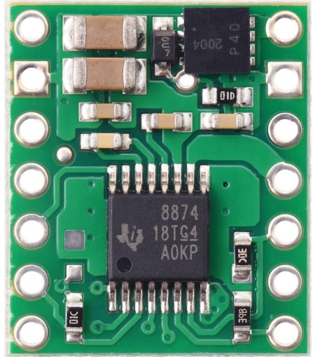
The DRV8874 from Texas Instruments is a high-performance brushed DC motor driver designed for a wide range of applications requiring precise control of motor speed and direction. It is commonly used in robotics, industrial automation, and consumer electronics. The DRV8874 simplifies the process of driving a DC motor by integrating most of the components required for motor control into a single IC, thus reducing the complexity and footprint of the motor control circuitry.
Explore Projects Built with DRV8874


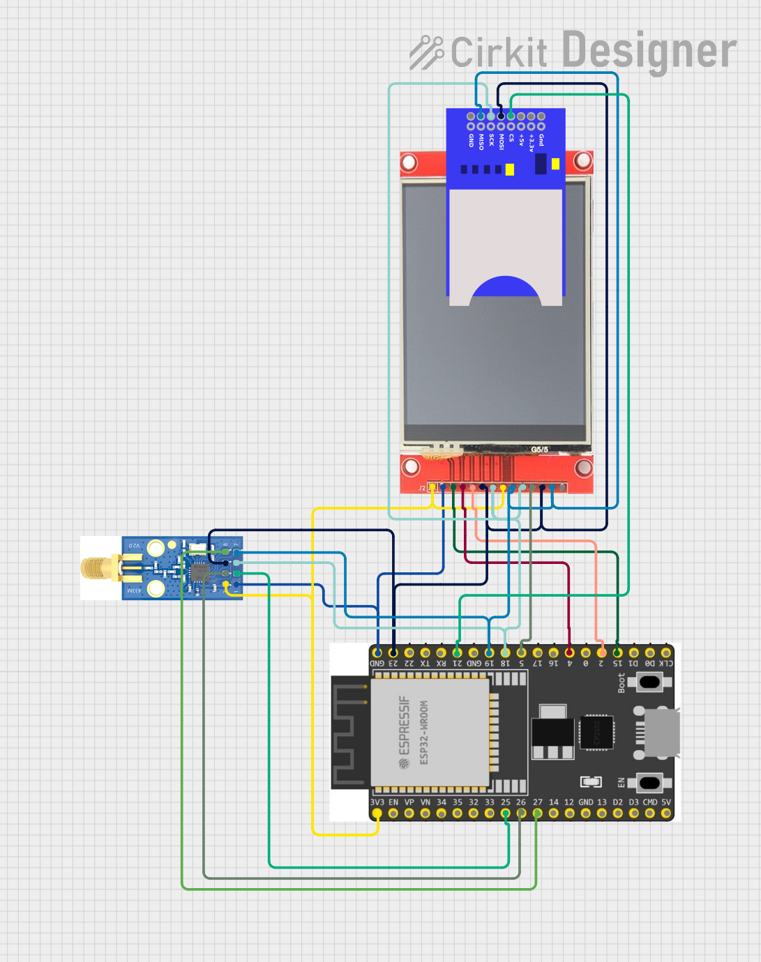
Explore Projects Built with DRV8874
Technical Specifications
Key Features
- Motor Type: Brushed DC
- Operating Voltage Range: 6.5 V to 45 V
- Output Current: Up to 3.5 A continuous, 5.8 A peak
- Protection Features: Overcurrent, overtemperature, undervoltage lockout
- Control Interface: PH/EN, PWM
- Package: HTSSOP, PowerPAD
Pin Configuration and Descriptions
| Pin Number | Name | Description |
|---|---|---|
| 1 | VM | Motor power supply voltage (6.5 V to 45 V) |
| 2 | GND | Ground |
| 3 | OUT1 | Motor output 1 |
| 4 | OUT2 | Motor output 2 |
| 5 | VPROPI | Proportional current regulation voltage input |
| 6 | ISENSE | Current sense output |
| 7 | nFAULT | Fault condition indicator |
| 8 | EN/IN1 | Enable/motor direction input 1 |
| 9 | PH/IN2 | Phase/motor direction input 2 |
| 10 | VREF | Reference voltage for current regulation |
| 11 | GND | Ground |
| 12 | VCP | Charge pump output |
| 13 | VCC | 3.3 V to 5 V logic supply voltage |
| 14 | SLEEP | Low-power sleep mode |
Usage Instructions
Connecting the DRV8874 to a Circuit
- Connect the motor to the OUT1 and OUT2 pins.
- Apply the motor power supply voltage (VM) to the VM pin and connect the ground (GND) pins to the system ground.
- Connect the logic supply voltage (VCC) to the VCC pin.
- Use the EN/IN1 and PH/IN2 pins to control the motor's direction and enable state.
- Optionally, connect a reference voltage to the VREF pin to set the current regulation threshold.
- Monitor the ISENSE pin for real-time current feedback.
- Connect the nFAULT pin to a microcontroller to detect fault conditions.
Control via Arduino UNO
// Define the control pins for the DRV8874
#define EN_IN1 2
#define PH_IN2 3

void setup() {
  // Set the control pins as outputs
  pinMode(EN_IN1, OUTPUT);
  pinMode(PH_IN2, OUTPUT);
}

void loop() {
  // Set the motor direction to clockwise
  digitalWrite(EN_IN1, HIGH);
  digitalWrite(PH_IN2, LOW);
  delay(1000); // Run the motor for 1 second

  // Set the motor direction to counter-clockwise
  digitalWrite(EN_IN1, HIGH);
  digitalWrite(PH_IN2, HIGH);
  delay(1000); // Run the motor for 1 second

  // Stop the motor
  digitalWrite(EN_IN1, LOW);
  delay(1000); // Stop the motor for 1 second
}
Important Considerations and Best Practices
- Ensure the power supply voltage and current do not exceed the specified limits.
- Use a proper decoupling capacitor close to the VM and VCC pins to minimize voltage spikes.
- Implement proper heat sinking if operating the motor driver at high currents.
- Use the nFAULT pin to implement fault handling in your control software.
Troubleshooting and FAQs
Common Issues
- Motor not running: Check power supply connections, ensure the EN/IN1 pin is set high to enable the motor driver.
- Overcurrent fault: Reduce the load on the motor or check for shorts in the motor wiring.
- Overtemperature fault: Ensure adequate cooling for the DRV8874, and check for excessive motor current draw.
FAQs
Q: Can the DRV8874 be used to drive two motors? A: No, the DRV8874 is designed to drive a single brushed DC motor.
Q: What is the function of the VREF pin? A: The VREF pin sets the reference voltage for the current regulation feature, allowing control over the maximum current supplied to the motor.
Q: How do I put the DRV8874 into sleep mode? A: Drive the SLEEP pin low to put the DRV8874 into a low-power sleep mode.
Q: How can I reverse the motor direction? A: Change the logic levels on the PH/IN2 and EN/IN1 pins to reverse the motor direction.
For further assistance or technical support, please contact Texas Instruments customer support or refer to the DRV8874 datasheet for more detailed information.