How to Use Flora SI1145 UV Sensor: Examples, Pinouts, and Specs
Introduction
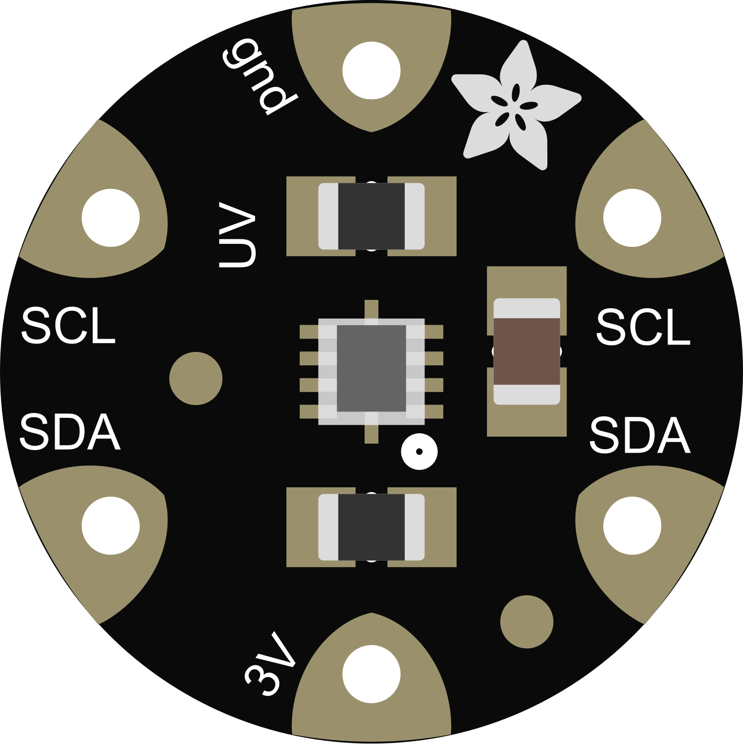
The Flora SI1145 UV Sensor is a versatile and compact sensor module capable of measuring UV index, ambient light intensity, and infrared (IR) light intensity. This sensor is particularly useful in wearable technology, environmental monitoring, and any application where tracking UV exposure or light levels is crucial.
Explore Projects Built with Flora SI1145 UV Sensor

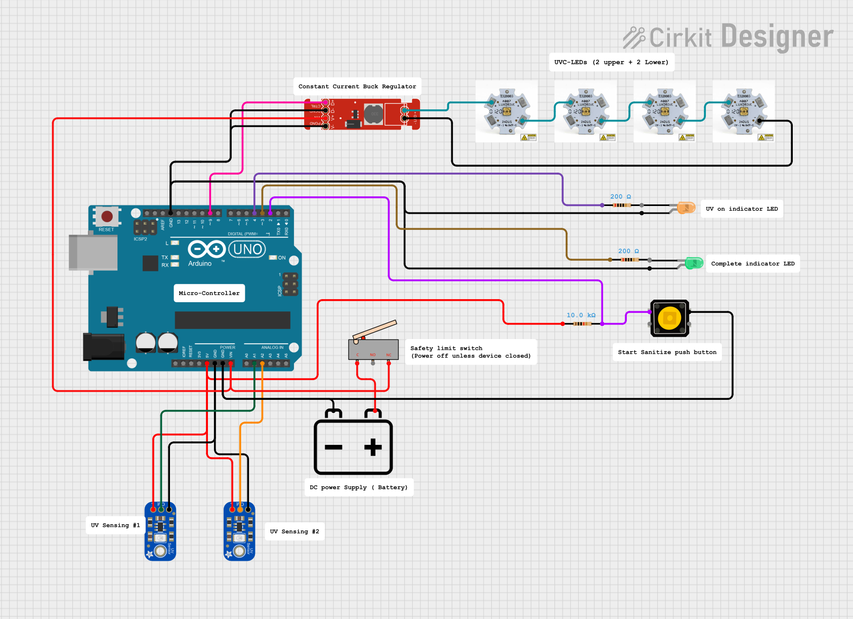
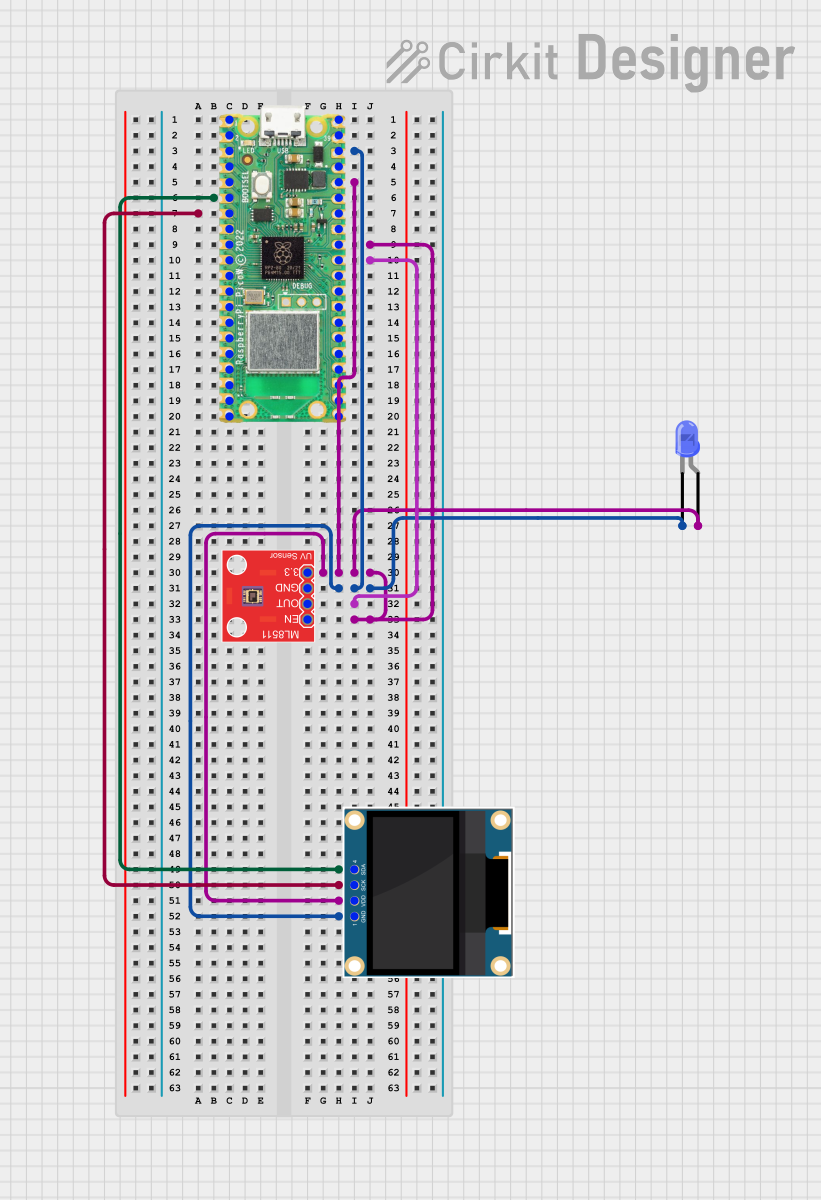
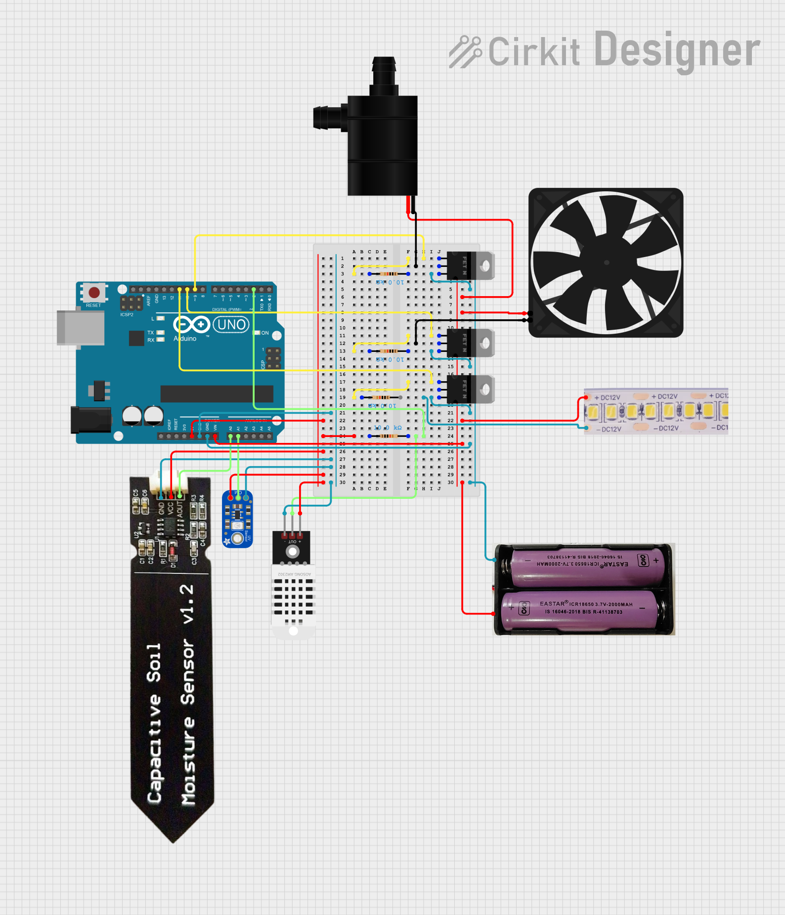
Explore Projects Built with Flora SI1145 UV Sensor
Common Applications and Use Cases
- Personal UV exposure monitoring devices
- Environmental monitoring stations
- Wearable electronics
- Smart home systems for light management
- Weather stations
Technical Specifications
Key Technical Details
- UV Index Measurement Range: 0 to 11+
- Ambient Light Intensity Range: 0 to 128,000 Lux
- IR Intensity Range: Dynamic; varies with ambient conditions
- Operating Voltage: 3.3V (Do not exceed 3.6V)
- Current Consumption: 0.5 mA (typical operation)
- Interface: I2C
- Operating Temperature Range: -40°C to 85°C
Pin Configuration and Descriptions
| Pin Number | Name | Description |
|---|---|---|
| 1 | VIN | Power supply (3.3V input) |
| 2 | GND | Ground connection |
| 3 | SCL | I2C clock line |
| 4 | SDA | I2C data line |
| 5 | INT | Interrupt pin (active low) |
Usage Instructions
How to Use the Component in a Circuit
- Power Connections: Connect the VIN pin to a 3.3V power source and the GND pin to the ground.
- I2C Connections: Connect the SCL and SDA pins to the I2C clock and data lines, respectively.
- Interrupt (Optional): The INT pin can be connected to a digital input on a microcontroller if interrupt-driven measurements are needed.
Important Considerations and Best Practices
- Ensure that the power supply does not exceed 3.6V to prevent damage to the sensor.
- Use pull-up resistors on the I2C lines if they are not already present on the microcontroller board.
- Avoid exposing the sensor to direct sunlight for extended periods to prevent sensor degradation.
- Calibrate the sensor in the environment where it will be used for accurate readings.
Example Code for Arduino UNO
#include <Wire.h>
#include "Adafruit_SI1145.h"

Adafruit_SI1145 uv = Adafruit_SI1145();

void setup() {
  Serial.begin(9600);
  if (!uv.begin()) {
    Serial.println("Didn't find Si1145");
    while (1);
  }
  Serial.println("Si1145 is ready!");
}

void loop() {
  float UVindex = uv.readUV();
  // The SI1145 gives UV index * 100, so divide by 100 to get the true UV index
  UVindex /= 100.0;
  Serial.print("UV Index: "); Serial.println(UVindex);

  // Read visible and IR light levels
  Serial.print("Visible: "); Serial.println(uv.readVisible());
  Serial.print("IR: "); Serial.println(uv.readIR());

  // Delay between readings
  delay(1000);
}
Troubleshooting and FAQs
Common Issues Users Might Face
- Incorrect Readings: Ensure that the sensor is not exposed to direct sunlight or high-intensity lights that could saturate the sensor.
- No Data on I2C: Check the connections and ensure that the correct I2C address is being used. Also, verify that pull-up resistors are in place if needed.
- Sensor Not Detected: Make sure that the sensor is properly powered and that the I2C lines are correctly connected.
Solutions and Tips for Troubleshooting
- Power Issues: Use a multimeter to verify that the sensor is receiving the correct voltage.
- Connection Issues: Double-check wiring, especially the I2C lines, and ensure that there are no loose connections.
- Code Issues: Verify that the library is correctly included and that the microcontroller is programmed with the correct code.
FAQs
Q: Can the sensor be used with a 5V microcontroller? A: Yes, but level shifters should be used on the I2C lines, and the sensor should still be powered with 3.3V.
Q: How can I extend the life of the sensor? A: Avoid prolonged exposure to extreme conditions, such as direct sunlight or high temperatures, and follow the recommended operating conditions.
Q: Is calibration required for the sensor? A: The sensor comes factory-calibrated, but for precise applications, you may need to calibrate it against a known light source.
Q: What is the I2C address of the Flora SI1145 UV Sensor? A: The default I2C address is 0x60.