How to Use EYE BLINK SENSOR: Examples, Pinouts, and Specs
Introduction
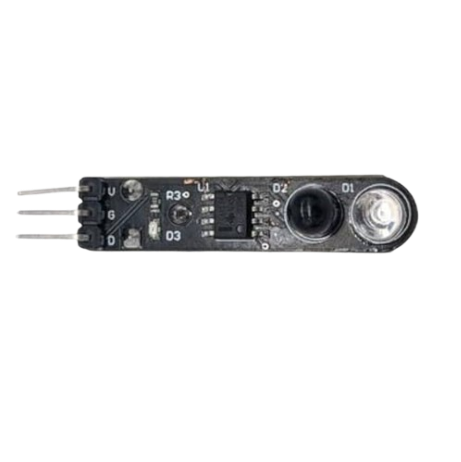
The EYE BLINK SENSOR (Manufacturer: EYE, Part ID: 1) is a compact and efficient device designed to detect eye blinks. It is widely used in assistive technologies, human-computer interaction systems, and wearable devices. By monitoring eye movements, this sensor enables hands-free control of electronic systems, making it an essential component in applications such as accessibility tools for individuals with disabilities, gaming interfaces, and fatigue detection systems.
Explore Projects Built with EYE BLINK SENSOR
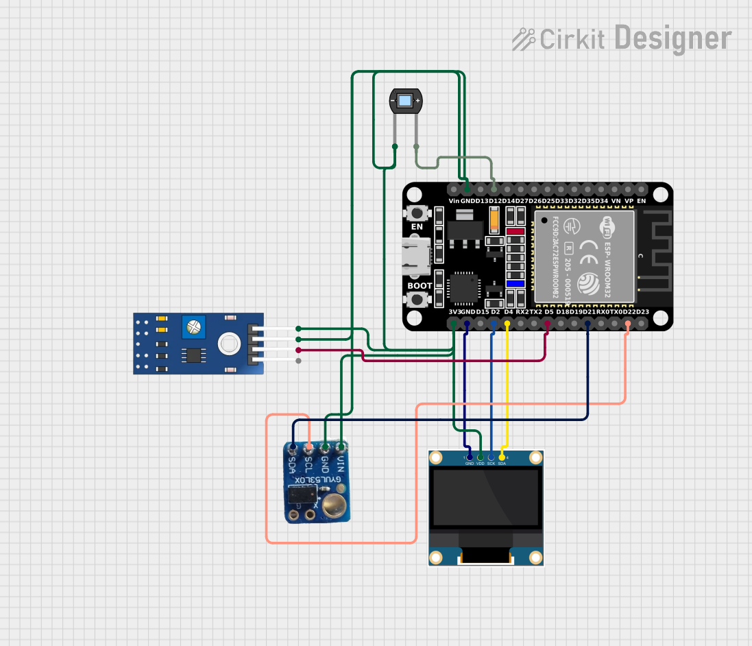
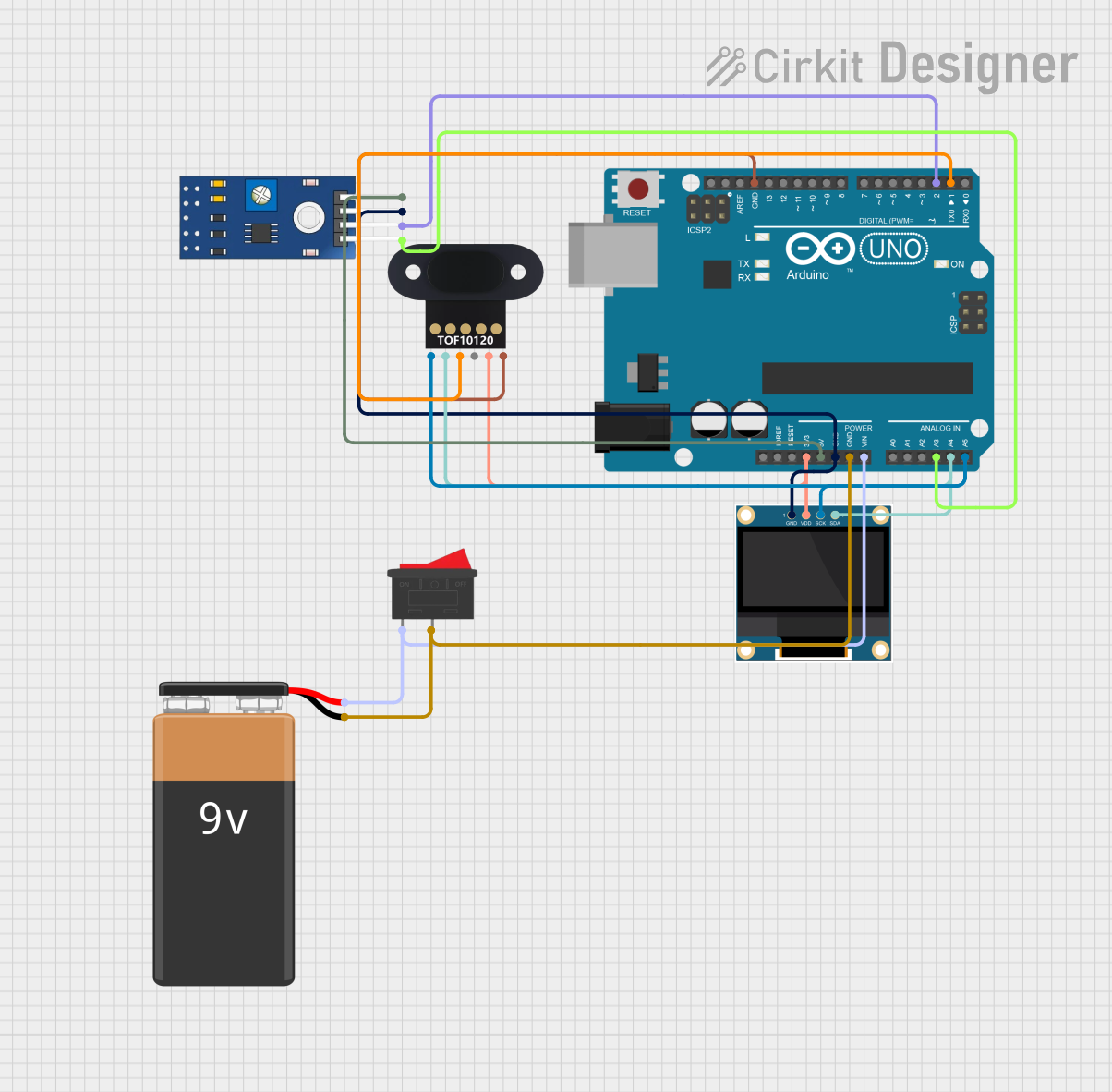

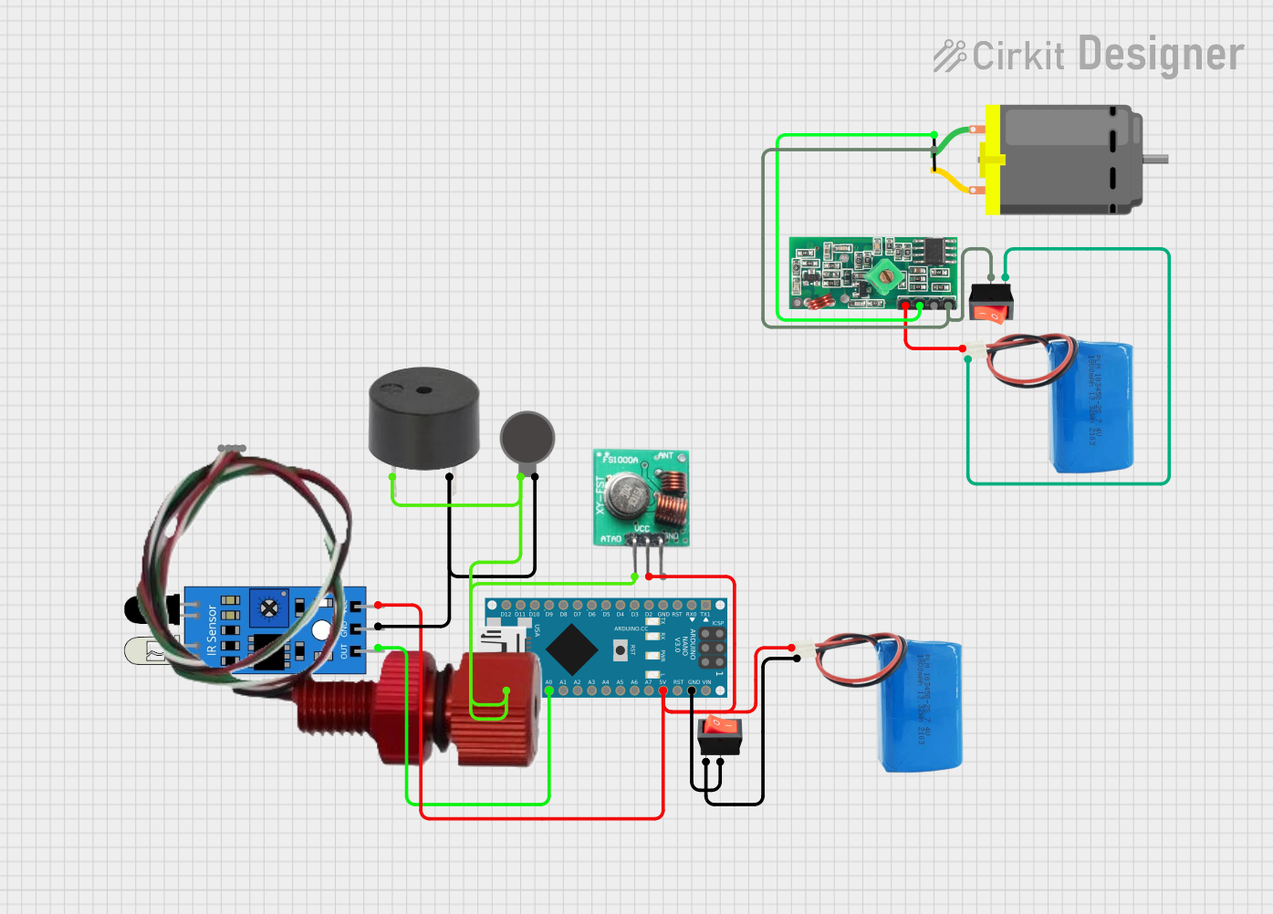
Explore Projects Built with EYE BLINK SENSOR
Common Applications and Use Cases
- Assistive Technology: Enables control of devices for individuals with limited mobility.
- Fatigue Monitoring: Detects drowsiness in drivers or machine operators.
- Human-Computer Interaction: Facilitates hands-free control in gaming or virtual reality systems.
- Wearable Devices: Integrates into smart glasses or headsets for gesture-based control.
Technical Specifications
The EYE BLINK SENSOR is designed for ease of integration and reliable performance. Below are its key technical details:
General Specifications
| Parameter | Value |
|---|---|
| Operating Voltage | 3.3V to 5V |
| Operating Current | < 10mA |
| Output Signal | Digital (High/Low) |
| Detection Range | 15mm to 25mm (from the sensor) |
| Response Time | < 100ms |
| Dimensions | 25mm x 20mm x 5mm |
| Operating Temperature | -10°C to 50°C |
Pin Configuration and Descriptions
The EYE BLINK SENSOR has a 3-pin interface for easy connection to microcontrollers or other devices.
| Pin Number | Pin Name | Description |
|---|---|---|
| 1 | VCC | Power supply input (3.3V to 5V) |
| 2 | GND | Ground connection |
| 3 | OUT | Digital output signal (High when blink detected) |
Usage Instructions
The EYE BLINK SENSOR is simple to use and can be integrated into a variety of circuits. Follow the steps below to use the sensor effectively:
Connecting the Sensor
- Power Supply: Connect the
VCCpin to a 3.3V or 5V power source and theGNDpin to the ground. - Output Signal: Connect the
OUTpin to a digital input pin on your microcontroller or other processing unit.
Example Circuit with Arduino UNO
Below is an example of how to connect the EYE BLINK SENSOR to an Arduino UNO:
- Connections:
VCC→ 5V on ArduinoGND→ GND on ArduinoOUT→ Digital Pin 2 on Arduino
Sample Code
// EYE BLINK SENSOR Example Code
// This code reads the sensor output and turns on an LED when a blink is detected.

const int sensorPin = 2;  // Pin connected to the sensor's OUT pin
const int ledPin = 13;    // Pin connected to the onboard LED

void setup() {
  pinMode(sensorPin, INPUT);  // Set sensor pin as input
  pinMode(ledPin, OUTPUT);    // Set LED pin as output
  Serial.begin(9600);         // Initialize serial communication
}

void loop() {
  int sensorValue = digitalRead(sensorPin);  // Read the sensor output

  if (sensorValue == HIGH) {
    // Blink detected, turn on LED
    digitalWrite(ledPin, HIGH);
    Serial.println("Blink detected!");
  } else {
    // No blink detected, turn off LED
    digitalWrite(ledPin, LOW);
  }

  delay(100);  // Small delay for stability
}
Important Considerations and Best Practices
- Placement: Ensure the sensor is positioned 15mm to 25mm from the eye for optimal detection.
- Ambient Light: Avoid direct exposure to strong light sources, as this may interfere with detection.
- Power Supply: Use a stable power source to prevent fluctuations in sensor performance.
- Calibration: If the sensor is not detecting blinks accurately, adjust its position or sensitivity (if adjustable).
Troubleshooting and FAQs
Common Issues and Solutions
Sensor Not Detecting Blinks:
- Ensure the sensor is within the specified detection range (15mm to 25mm).
- Check the power supply voltage (3.3V to 5V) and connections.
- Avoid obstructions or excessive ambient light near the sensor.
False Positives or Noise in Output:
- Shield the sensor from direct sunlight or strong artificial light.
- Use a pull-down resistor on the
OUTpin to stabilize the signal.
No Output Signal:
- Verify the connections to the microcontroller or processing unit.
- Test the sensor with a multimeter to ensure it is functioning.
FAQs
Q1: Can the sensor detect rapid blinks?
A1: Yes, the sensor has a response time of less than 100ms, making it capable of detecting rapid blinks.
Q2: Is the sensor compatible with 3.3V systems?
A2: Yes, the sensor operates with both 3.3V and 5V power supplies.
Q3: Can the sensor be used in outdoor environments?
A3: The sensor can operate in temperatures from -10°C to 50°C, but avoid direct sunlight or extreme lighting conditions for accurate detection.
Q4: How do I integrate the sensor with other microcontrollers?
A4: Connect the OUT pin to a digital input pin on your microcontroller and follow the same logic as shown in the Arduino example.
By following this documentation, you can effectively integrate and use the EYE BLINK SENSOR in your projects.