How to Use AHT10: Examples, Pinouts, and Specs
Introduction
The AHT10 is a digital temperature and humidity sensor designed for precise environmental monitoring. It integrates a capacitive humidity sensor and a high-performance temperature sensor, providing accurate and reliable measurements. The AHT10 features a built-in I2C interface, making it easy to connect to microcontrollers and other digital systems. Its compact size, low power consumption, and high precision make it ideal for a wide range of applications.
Explore Projects Built with AHT10
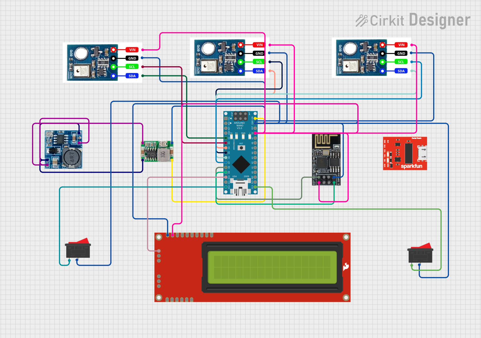
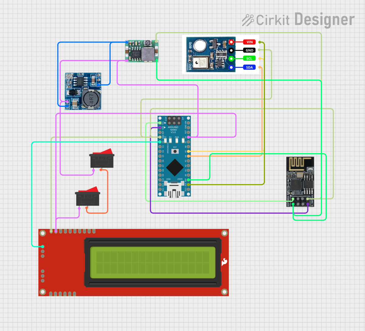
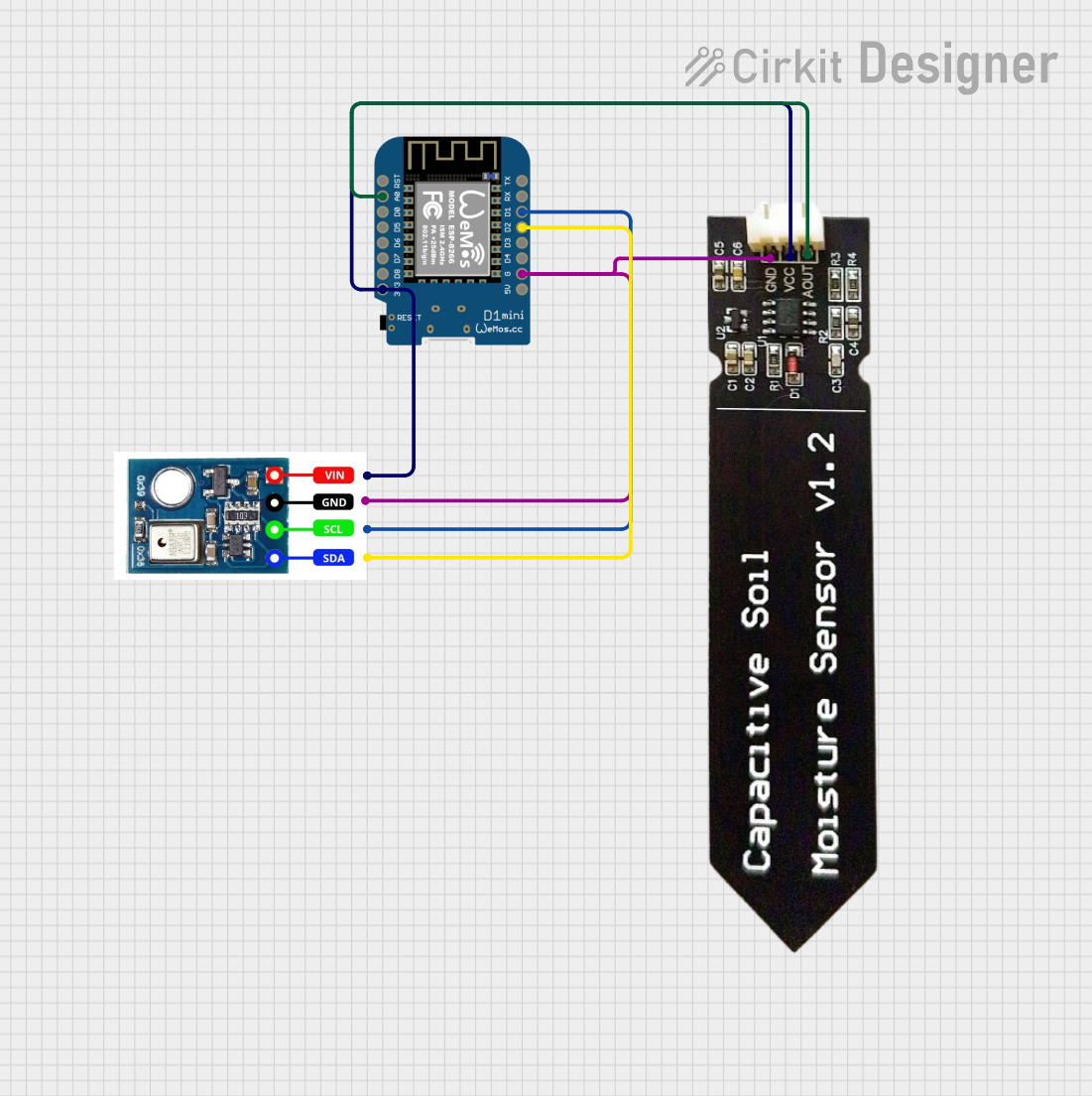
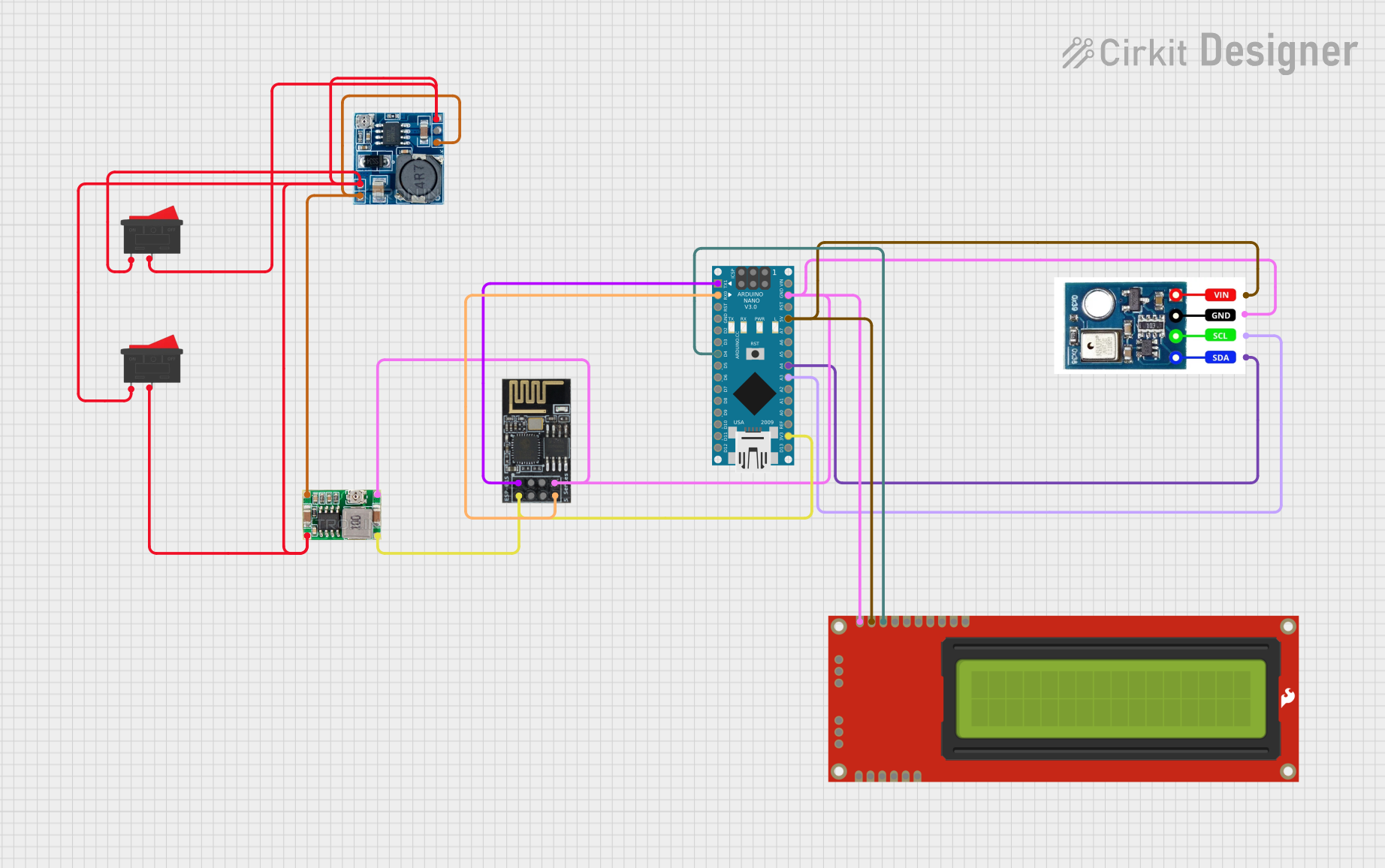
Explore Projects Built with AHT10
Common Applications and Use Cases
- Weather monitoring systems
- HVAC (Heating, Ventilation, and Air Conditioning) control
- IoT (Internet of Things) devices
- Industrial and home automation
- Environmental data logging
Technical Specifications
The AHT10 sensor is designed to deliver high accuracy and reliability. Below are its key technical details:
| Parameter | Value |
|---|---|
| Supply Voltage (VDD) | 2.0V to 5.5V |
| Operating Current | 0.25 mA (average) |
| Standby Current | < 0.01 mA |
| Humidity Measurement Range | 0% to 100% RH |
| Humidity Accuracy | ±2% RH (typical) |
| Temperature Range | -40°C to 85°C |
| Temperature Accuracy | ±0.3°C (typical) |
| Communication Interface | I2C |
| I2C Address | 0x38 |
| Response Time | < 8 seconds |
| Dimensions | 4.0mm x 5.0mm x 1.6mm |
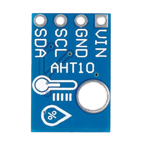
Pin Configuration and Descriptions
The AHT10 sensor has four pins, as described in the table below:
| Pin | Name | Description |
|---|---|---|
| 1 | VDD | Power supply (2.0V to 5.5V) |
| 2 | GND | Ground |
| 3 | SCL | I2C clock line |
| 4 | SDA | I2C data line |
Usage Instructions
The AHT10 sensor is straightforward to use in a circuit, thanks to its I2C interface. Below are the steps and considerations for integrating the AHT10 into your project:
Connecting the AHT10 to a Microcontroller
- Power Supply: Connect the VDD pin to a 3.3V or 5V power source, depending on your system's voltage level. Connect the GND pin to the ground.
- I2C Lines: Connect the SCL and SDA pins to the corresponding I2C clock and data lines on your microcontroller. Use pull-up resistors (typically 4.7kΩ) on the SCL and SDA lines if they are not already present in your circuit.
- Address: The AHT10 has a fixed I2C address of
0x38.
Example Code for Arduino UNO
Below is an example Arduino sketch to read temperature and humidity data from the AHT10 sensor:
#include <Wire.h>

// AHT10 I2C address
#define AHT10_ADDRESS 0x38

void setup() {
  Wire.begin(); // Initialize I2C communication
  Serial.begin(9600); // Start serial communication for debugging

  // Initialize the AHT10 sensor
  Wire.beginTransmission(AHT10_ADDRESS);
  Wire.write(0xE1); // Send initialization command
  Wire.endTransmission();
  delay(10); // Wait for the sensor to initialize
}

void loop() {
  // Request data from the AHT10 sensor
  Wire.beginTransmission(AHT10_ADDRESS);
  Wire.write(0xAC); // Trigger measurement command
  Wire.write(0x33); // Data byte 1
  Wire.write(0x00); // Data byte 2
  Wire.endTransmission();
  delay(100); // Wait for measurement to complete

  // Read 6 bytes of data from the sensor
  Wire.requestFrom(AHT10_ADDRESS, 6);
  if (Wire.available() == 6) {
    uint8_t data[6];
    for (int i = 0; i < 6; i++) {
      data[i] = Wire.read();
    }

    // Process the received data
    uint32_t rawHumidity = ((uint32_t)data[1] << 12) |
                           ((uint32_t)data[2] << 4) |
                           (data[3] >> 4);
    uint32_t rawTemperature = ((uint32_t)(data[3] & 0x0F) << 16) |
                               ((uint32_t)data[4] << 8) |
                               data[5];

    // Convert raw data to actual values
    float humidity = (rawHumidity * 100.0) / 1048576.0;
    float temperature = (rawTemperature * 200.0) / 1048576.0 - 50.0;

    // Print the results
    Serial.print("Humidity: ");
    Serial.print(humidity);
    Serial.println(" %");
    Serial.print("Temperature: ");
    Serial.print(temperature);
    Serial.println(" °C");
  }

  delay(2000); // Wait before the next reading
}
Important Considerations and Best Practices
- Power Supply: Ensure a stable power supply to avoid measurement errors.
- I2C Pull-Up Resistors: Use appropriate pull-up resistors on the I2C lines if not already included in your circuit.
- Initialization: Always initialize the sensor before taking measurements.
- Environmental Factors: Avoid exposing the sensor to extreme conditions (e.g., condensation or dust) to maintain accuracy and longevity.
Troubleshooting and FAQs
Common Issues and Solutions
No Data from the Sensor:
- Ensure the I2C connections (SCL and SDA) are correct.
- Verify that the pull-up resistors are properly connected.
- Check the power supply voltage (2.0V to 5.5V).
Inaccurate Readings:
- Ensure the sensor is not exposed to condensation or contaminants.
- Allow the sensor to stabilize in the environment before taking measurements.
I2C Communication Errors:
- Verify the I2C address (
0x38) is correct. - Check for conflicting devices on the I2C bus.
- Verify the I2C address (
FAQs
Q: Can the AHT10 operate at 5V?
A: Yes, the AHT10 supports a supply voltage range of 2.0V to 5.5V, making it compatible with both 3.3V and 5V systems.
Q: Do I need to calibrate the AHT10?
A: No, the AHT10 is factory-calibrated and does not require additional calibration.
Q: What is the typical response time of the AHT10?
A: The AHT10 has a response time of less than 8 seconds under normal conditions.