How to Use RELAY RED: Examples, Pinouts, and Specs
Introduction
A relay is an electromechanical switch that uses an electromagnetic coil to open or close contacts, enabling the control of a high-power circuit with a low-power signal. The "RELAY RED" designation may refer to a specific type, color-coded for identification, or a particular rating of the relay. Relays are widely used in applications where electrical isolation, high-power switching, or remote control of circuits is required.
Explore Projects Built with RELAY RED
Explore Projects Built with RELAY RED
Common Applications and Use Cases
- Home automation systems (e.g., controlling lights, fans, or appliances)
- Automotive electronics (e.g., controlling headlights, horns, or motors)
- Industrial control systems (e.g., motor starters, solenoids, or pumps)
- Microcontroller-based projects (e.g., Arduino or Raspberry Pi applications)
- Safety circuits requiring electrical isolation
Technical Specifications
Key Technical Details
- Coil Voltage: 5V DC (typical for microcontroller applications)
- Contact Rating: 10A at 250V AC or 10A at 30V DC
- Coil Resistance: ~70Ω (for 5V coil)
- Switching Type: SPDT (Single Pole Double Throw)
- Isolation: Electrical isolation between control and load circuits
- Operating Temperature: -40°C to 85°C
- Dimensions: 28mm x 10mm x 15mm (approximate)
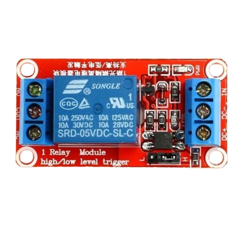
Pin Configuration and Descriptions
The RELAY RED typically has 5 pins, as described in the table below:
| Pin Number | Name | Description |
|---|---|---|
| 1 | Coil (+) | Positive terminal of the electromagnetic coil (connect to control voltage) |
| 2 | Coil (-) | Negative terminal of the electromagnetic coil (connect to ground) |
| 3 | Common (COM) | Common terminal for the switching contacts |
| 4 | Normally Open (NO) | Contact that remains open until the relay is activated |
| 5 | Normally Closed (NC) | Contact that remains closed until the relay is activated |
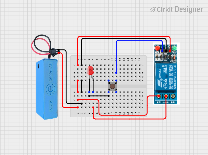
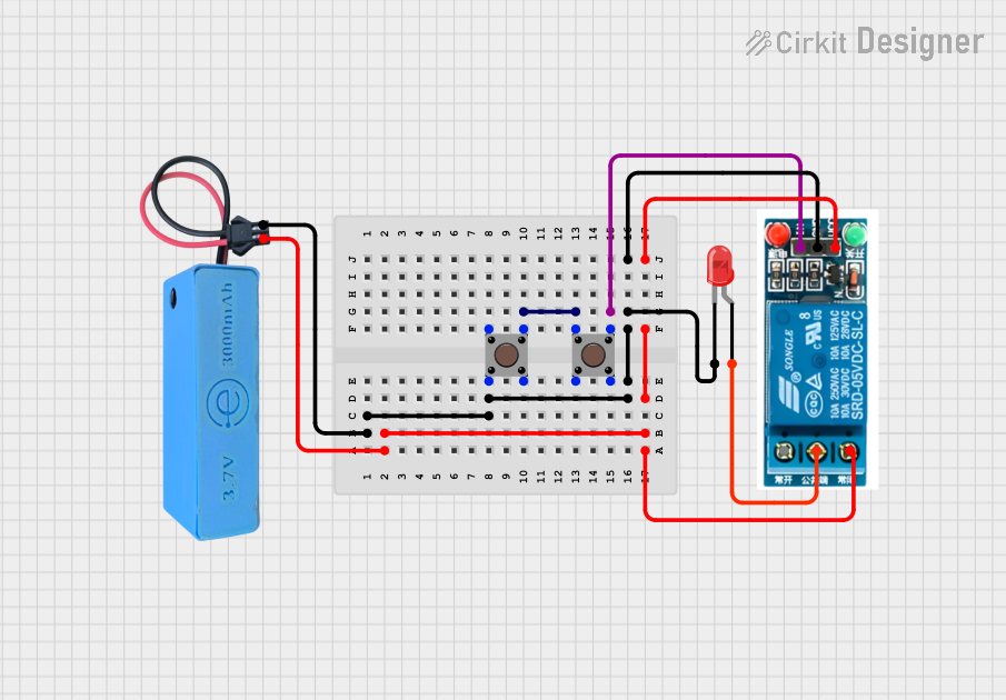
Usage Instructions
How to Use the Component in a Circuit
- Power the Coil: Connect the coil pins (1 and 2) to a 5V DC power source. Use a transistor or MOSFET to control the coil if using a microcontroller.
- Connect the Load:
- Connect the load to the Common (COM) pin (3).
- Use the Normally Open (NO) pin (4) if you want the load to turn on when the relay is activated.
- Use the Normally Closed (NC) pin (5) if you want the load to turn off when the relay is activated.
- Control the Relay: Use a low-power control signal (e.g., from an Arduino) to energize the coil and switch the contacts.
Important Considerations and Best Practices
- Flyback Diode: Always connect a flyback diode across the coil terminals to protect the circuit from voltage spikes when the relay is deactivated.
- Current Ratings: Ensure the load current does not exceed the relay's contact rating (10A).
- Isolation: Use optocouplers or transistors to isolate the control circuit from the high-power load circuit.
- Power Supply: Provide a stable 5V DC supply to the coil for reliable operation.
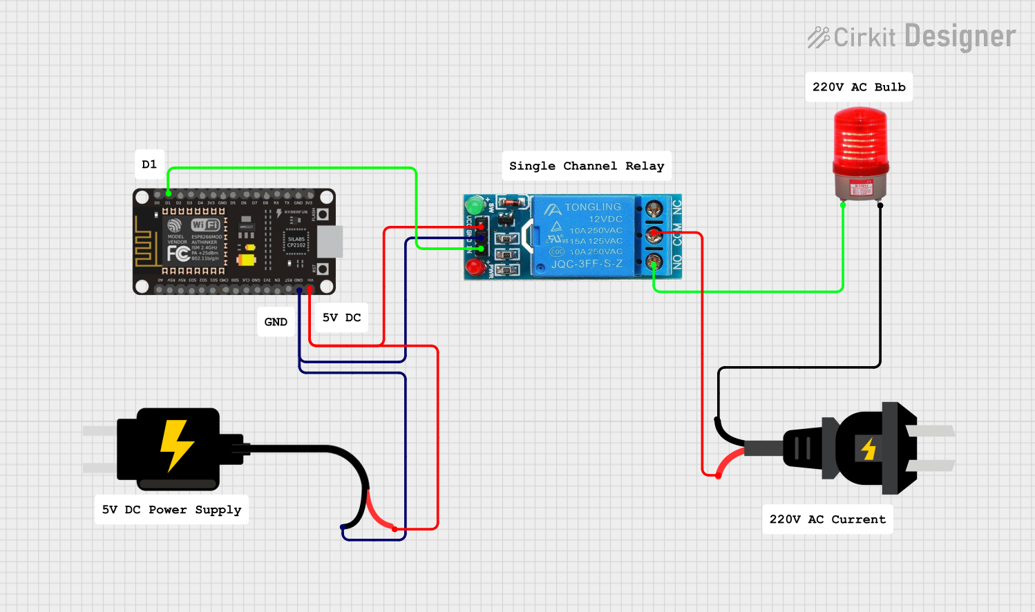
Example: Connecting RELAY RED to an Arduino UNO
Below is an example of how to control the RELAY RED using an Arduino UNO:
// Define the pin connected to the relay control
const int relayPin = 7;

void setup() {
  pinMode(relayPin, OUTPUT); // Set the relay pin as an output
  digitalWrite(relayPin, LOW); // Ensure the relay is off at startup
}

void loop() {
  digitalWrite(relayPin, HIGH); // Activate the relay
  delay(1000); // Keep the relay on for 1 second
  digitalWrite(relayPin, LOW); // Deactivate the relay
  delay(1000); // Keep the relay off for 1 second
}
Note: Use a transistor (e.g., 2N2222) between the Arduino and the relay coil to handle the current required by the relay.
Troubleshooting and FAQs
Common Issues and Solutions
Relay Not Activating:
- Cause: Insufficient voltage or current to the coil.
- Solution: Verify the power supply and ensure the control circuit can provide enough current.
Relay Stuck in One State:
- Cause: Damaged contacts or coil.
- Solution: Check for physical damage or replace the relay.
Voltage Spikes Damaging the Circuit:
- Cause: Lack of a flyback diode across the coil.
- Solution: Add a flyback diode (e.g., 1N4007) across the coil terminals.
Load Not Switching Properly:
- Cause: Incorrect wiring of the load to the relay contacts.
- Solution: Double-check the connections to the COM, NO, and NC pins.
FAQs
Q1: Can I use the RELAY RED with a 3.3V microcontroller?
A1: Yes, but you will need a transistor or MOSFET to drive the 5V relay coil from the 3.3V control signal.
Q2: What is the purpose of the flyback diode?
A2: The flyback diode protects the control circuit from voltage spikes generated when the relay coil is de-energized.
Q3: Can the RELAY RED switch both AC and DC loads?
A3: Yes, it can switch AC loads up to 250V and DC loads up to 30V, provided the current does not exceed 10A.
Q4: How do I know if the relay is activated?
A4: Many relays, including the RELAY RED, have a built-in LED indicator that lights up when the relay is activated.