How to Use INA228: Examples, Pinouts, and Specs
Introduction
The INA228 is a high-precision, low-power current shunt monitor designed to measure current, voltage, and power in high-performance applications. It provides a digital output proportional to the current flowing through an external shunt resistor. With its wide common-mode voltage range and integrated ADC, the INA228 is ideal for applications requiring accurate power monitoring, such as battery management systems, server power supplies, and industrial automation.
Explore Projects Built with INA228

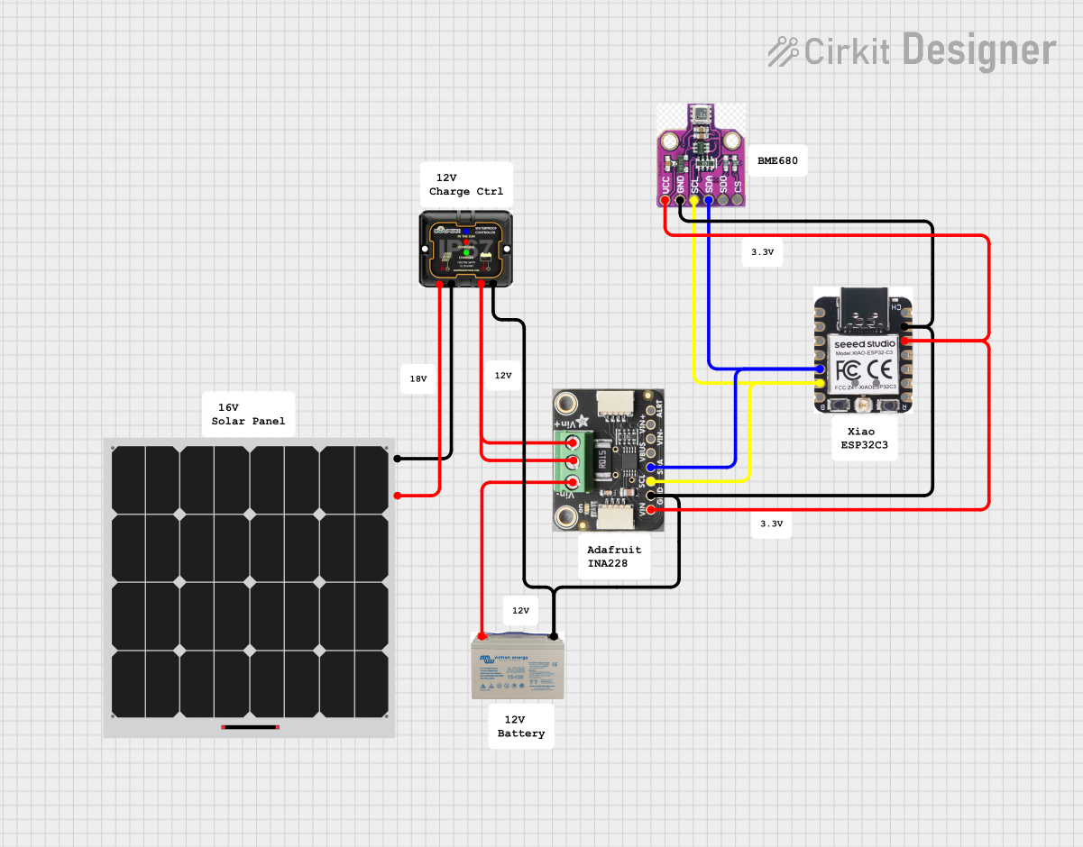
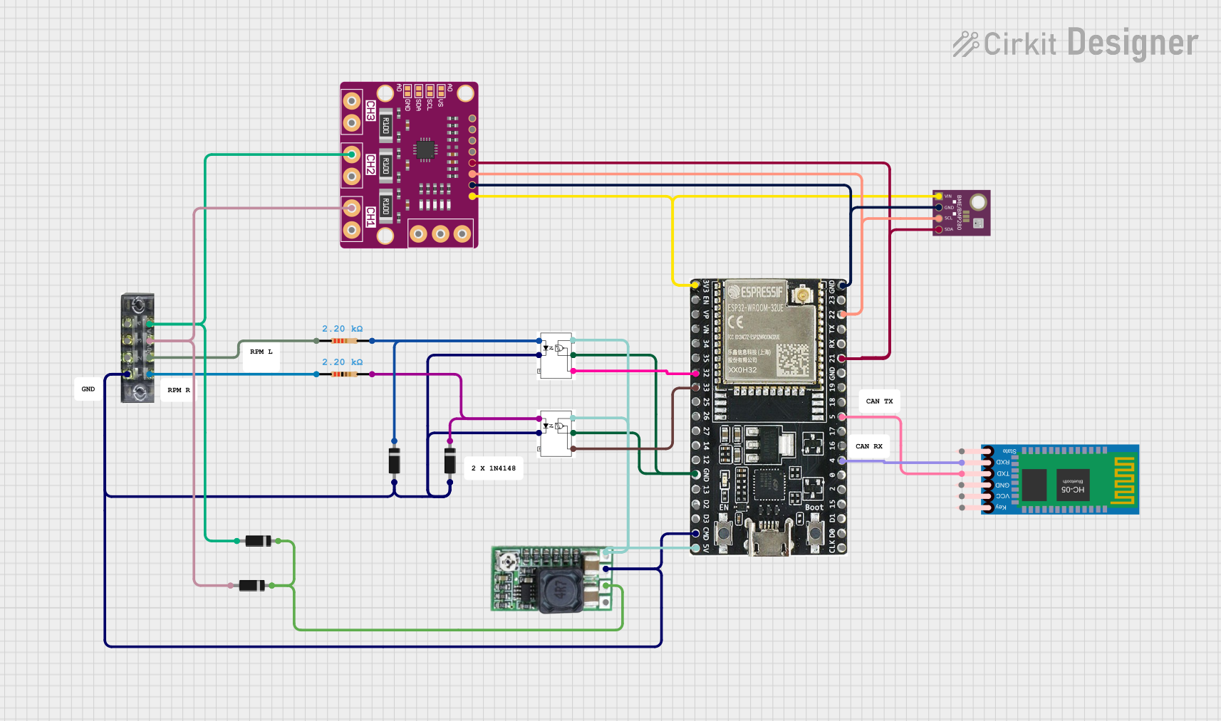
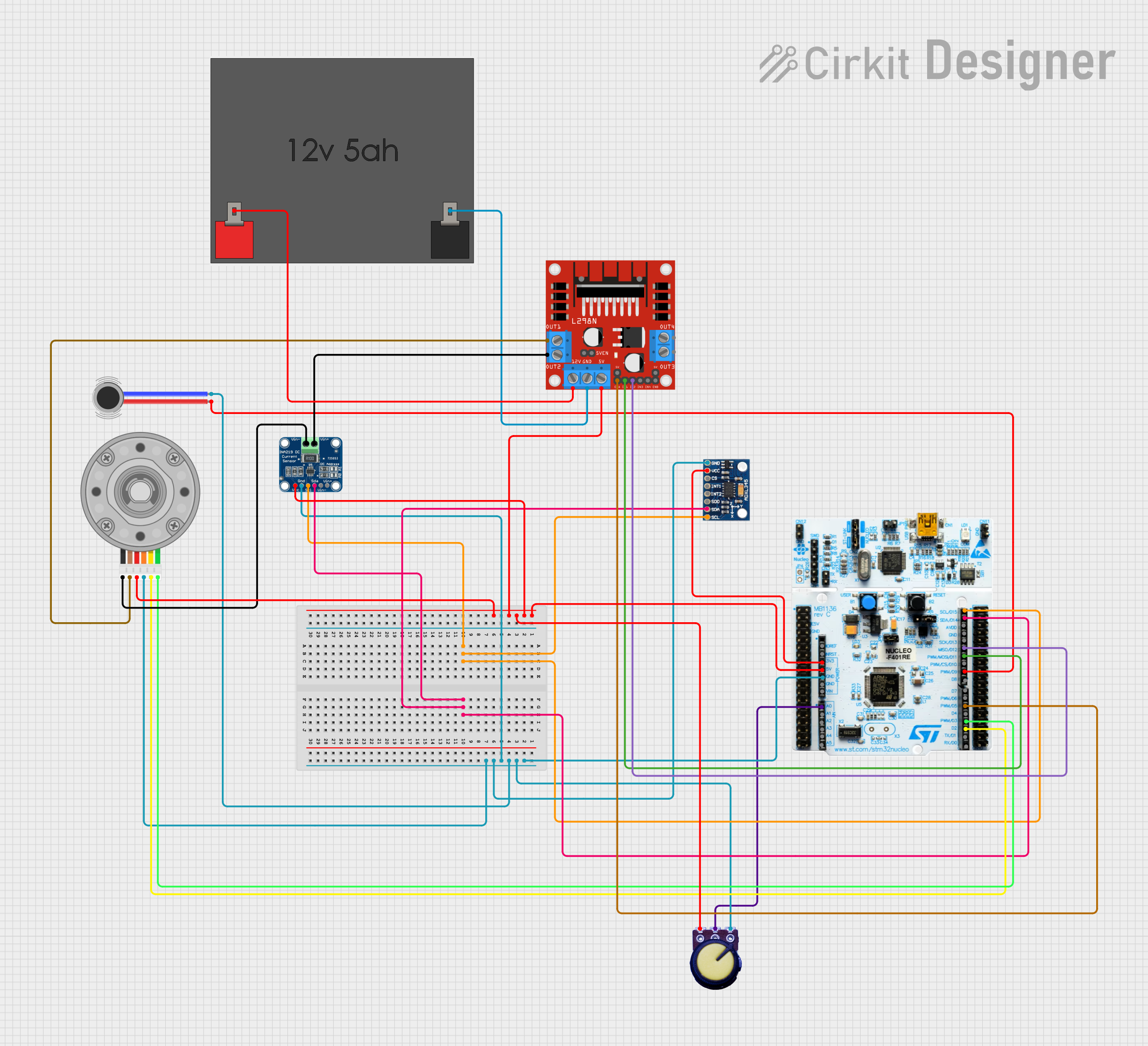
Explore Projects Built with INA228
Common Applications
- Battery management systems
- Power monitoring in servers and data centers
- Solar inverters and energy storage systems
- Industrial automation and motor control
- Electric vehicle (EV) power systems
Technical Specifications
The INA228 offers robust performance and flexibility for a variety of applications. Below are its key technical specifications:
| Parameter | Value |
|---|---|
| Supply Voltage (VCC) | 2.7 V to 5.5 V |
| Common-Mode Voltage Range | -0.3 V to +85 V |
| Input Offset Voltage | ±10 µV (typical) |
| Shunt Voltage Range | ±163.84 mV |
| ADC Resolution | 20 bits |
| Current Measurement Range | Configurable based on external shunt resistor |
| Power Consumption | 300 µA (typical) |
| Communication Interface | I²C or SMBus-compatible |
| Operating Temperature Range | -40°C to +125°C |
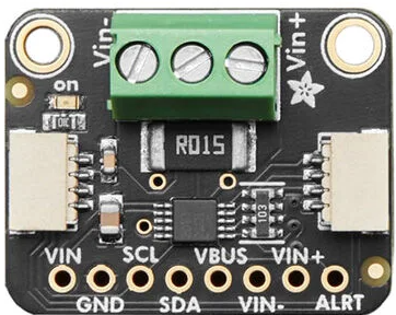
Pin Configuration and Descriptions
The INA228 is typically available in a small package, such as a WSON-10. Below is the pinout and description:
| Pin Number | Pin Name | Description |
|---|---|---|
| 1 | VIN+ | Positive input for differential shunt voltage measurement. |
| 2 | VIN- | Negative input for differential shunt voltage measurement. |
| 3 | GND | Ground connection. |
| 4 | SCL | Serial clock input for I²C/SMBus communication. |
| 5 | SDA | Serial data input/output for I²C/SMBus communication. |
| 6 | ALERT | Alert output pin for overcurrent, overvoltage, or other fault conditions. |
| 7 | VCC | Power supply input (2.7 V to 5.5 V). |
| 8 | ADDR | Address selection pin for I²C communication. |
| 9 | NC | No connection (leave floating or connect to GND). |
| 10 | NC | No connection (leave floating or connect to GND). |
Usage Instructions
The INA228 is straightforward to integrate into a circuit for current, voltage, and power monitoring. Below are the steps and considerations for using the component:
Circuit Integration
Shunt Resistor Selection:
- Choose a shunt resistor with a low resistance value to minimize power loss.
- Ensure the resistor's power rating can handle the maximum expected current.
- The INA228 measures the voltage drop across this resistor to calculate current.
Power Supply:
- Connect the VCC pin to a stable 2.7 V to 5.5 V power source.
- Decouple the power supply with a 0.1 µF ceramic capacitor close to the VCC pin.
I²C Communication:
- Connect the SCL and SDA pins to the corresponding I²C lines of the microcontroller.
- Use pull-up resistors (typically 4.7 kΩ) on the SCL and SDA lines.
Alert Pin (Optional):
- The ALERT pin can be used to signal fault conditions. Connect it to a microcontroller GPIO pin if needed.
Address Configuration:
- Use the ADDR pin to set the I²C address of the INA228. Refer to the datasheet for address selection details.
Example Arduino Code
The INA228 can be interfaced with an Arduino UNO using the I²C protocol. Below is an example code snippet to read shunt voltage and calculate current:
#include <Wire.h>

// INA228 I2C address (default: 0x40, adjust if ADDR pin is configured differently)
#define INA228_ADDRESS 0x40

// Register addresses (refer to the INA228 datasheet for details)
#define REG_SHUNT_VOLTAGE 0x04

// Shunt resistor value in ohms (adjust based on your circuit)
#define SHUNT_RESISTOR 0.01

void setup() {
  Wire.begin(); // Initialize I2C communication
  Serial.begin(9600); // Initialize serial communication for debugging
}

void loop() {
  float shuntVoltage = readShuntVoltage(); // Read shunt voltage
  float current = shuntVoltage / SHUNT_RESISTOR; // Calculate current

  // Print the results
  Serial.print("Shunt Voltage (mV): ");
  Serial.println(shuntVoltage * 1000); // Convert to millivolts
  Serial.print("Current (A): ");
  Serial.println(current);

  delay(1000); // Wait 1 second before the next reading
}

float readShuntVoltage() {
  Wire.beginTransmission(INA228_ADDRESS);
  Wire.write(REG_SHUNT_VOLTAGE); // Point to the shunt voltage register
  Wire.endTransmission(false); // Send repeated start condition
  Wire.requestFrom(INA228_ADDRESS, 2); // Request 2 bytes of data

  if (Wire.available() == 2) {
    uint16_t rawData = (Wire.read() << 8) | Wire.read(); // Combine MSB and LSB
    return rawData * 0.00000125; // Convert to volts (LSB = 1.25 µV)
  }

  return 0.0; // Return 0 if no data is available
}
Best Practices
- Use a high-precision, low-temperature-coefficient shunt resistor for accurate measurements.
- Keep the traces between the shunt resistor and the INA228 as short as possible to minimize noise.
- Ensure proper decoupling of the power supply to avoid voltage fluctuations.
Troubleshooting and FAQs
Common Issues
No Communication with the INA228:
- Verify the I²C address matches the configuration of the ADDR pin.
- Check the pull-up resistors on the SCL and SDA lines.
Incorrect Current Measurements:
- Ensure the shunt resistor value is correctly defined in the code.
- Verify the connections to the VIN+ and VIN- pins are secure and correct.
Alert Pin Not Functioning:
- Confirm the ALERT pin is configured correctly in the microcontroller code.
- Check the fault thresholds programmed into the INA228.
FAQs
Q: Can the INA228 measure bidirectional current?
A: Yes, the INA228 can measure both positive and negative currents, depending on the direction of current flow through the shunt resistor.
Q: What is the maximum current the INA228 can measure?
A: The maximum measurable current depends on the shunt resistor value and the ±163.84 mV shunt voltage range. For example, with a 0.01 Ω resistor, the maximum current is ±16.384 A.
Q: Is the INA228 suitable for high-voltage applications?
A: Yes, the INA228 supports a common-mode voltage range of -0.3 V to +85 V, making it suitable for high-voltage systems.
Q: Can I use the INA228 with a 3.3 V microcontroller?
A: Yes, the INA228 operates with a supply voltage of 2.7 V to 5.5 V and is compatible with 3.3 V logic levels.