Cirkit Designer Logo
Cirkit Designer
Your all-in-one circuit design IDE
Home / 
Component Documentation

How to Use PIXHAWK 2.4.8 DRONE CONTROLLER: Examples, Pinouts, and Specs

Image of PIXHAWK 2.4.8 DRONE CONTROLLER
Cirkit Designer LogoDesign with PIXHAWK 2.4.8 DRONE CONTROLLER in Cirkit Designer

Introduction

The PIXHAWK 2.4.8 Drone Controller is a versatile and powerful flight control hardware designed for drones and UAVs. It features advanced autopilot capabilities, support for a wide range of sensors, and compatibility with multiple software platforms such as PX4 and ArduPilot. This controller is widely used in both hobbyist and professional drone applications due to its reliability, flexibility, and robust performance.

Explore Projects Built with PIXHAWK 2.4.8 DRONE CONTROLLER

Use Cirkit Designer to design, explore, and prototype these projects online. Some projects support real-time simulation. Click "Open Project" to start designing instantly!
Raspberry Pi-Controlled Drone with Brushless Motors and Camera Module
Image of ROV: A project utilizing PIXHAWK 2.4.8 DRONE CONTROLLER in a practical application
This circuit is designed for a multi-motor application, likely a drone or a similar vehicle, featuring eight brushless motors controlled by two 4-in-1 electronic speed controllers (ESCs). The ESCs are powered by a 3s2p 18650 battery pack and interfaced with a Pixhawk flight controller for motor management. Additionally, the system includes a Raspberry Pi 4B for advanced processing and control, which is connected to a NoIR camera module and a cooling fan, and a power module to supply and monitor the power to the Pixhawk.
Cirkit Designer LogoOpen Project in Cirkit Designer
Battery-Powered BLDC Motor Control System with KK2.1.5 Flight Controller
Image of broncsDrone: A project utilizing PIXHAWK 2.4.8 DRONE CONTROLLER in a practical application
This circuit is a quadcopter control system that includes a LiPo battery, four BLDC motors, four ESCs, a KK2.1.5 flight controller, and an FS-R6B receiver. The KK2.1.5 flight controller manages the ESCs and motors based on input signals from the receiver, which is powered by the LiPo battery.
Cirkit Designer LogoOpen Project in Cirkit Designer
ESP32-Controlled Quadcopter with MPU-6050 IMU and ESP32-CAM
Image of drone circuit: A project utilizing PIXHAWK 2.4.8 DRONE CONTROLLER in a practical application
This circuit appears to be a control system for a quadcopter drone, featuring four brushless motors each connected to its own electronic speed controller (ESC). The ESCs are interfaced with an ESP32 microcontroller for signal control, and the system includes an MPU-6050 for motion tracking, a PDB XT60 for power distribution, and a Lipo battery as the power source. Additionally, there is an ESP32-CAM module for capturing images, potentially for surveillance or monitoring purposes.
Cirkit Designer LogoOpen Project in Cirkit Designer
ESP32-Controlled Quadcopter with GPS, MPU-6050, and ESP32-CAM
Image of drone: A project utilizing PIXHAWK 2.4.8 DRONE CONTROLLER in a practical application
This circuit is designed for a quadcopter drone with four brushless motors, each controlled by an individual Electronic Speed Controller (ESC). The ESCs receive power from a LiPo battery through a Power Distribution Board (PDB) and are interfaced with an ESP32 microcontroller for signal control. Additional components include an MPU-6050 for motion tracking, a GPS module for positioning, an HC-SR04 ultrasonic sensor for distance measurement, and an ESP32-CAM for image capture, all interfaced with the ESP32 microcontroller which manages sensor data processing and wireless communication.
Cirkit Designer LogoOpen Project in Cirkit Designer

Explore Projects Built with PIXHAWK 2.4.8 DRONE CONTROLLER

Use Cirkit Designer to design, explore, and prototype these projects online. Some projects support real-time simulation. Click "Open Project" to start designing instantly!
Image of ROV: A project utilizing PIXHAWK 2.4.8 DRONE CONTROLLER in a practical application
Raspberry Pi-Controlled Drone with Brushless Motors and Camera Module
This circuit is designed for a multi-motor application, likely a drone or a similar vehicle, featuring eight brushless motors controlled by two 4-in-1 electronic speed controllers (ESCs). The ESCs are powered by a 3s2p 18650 battery pack and interfaced with a Pixhawk flight controller for motor management. Additionally, the system includes a Raspberry Pi 4B for advanced processing and control, which is connected to a NoIR camera module and a cooling fan, and a power module to supply and monitor the power to the Pixhawk.
Cirkit Designer LogoOpen Project in Cirkit Designer
Image of broncsDrone: A project utilizing PIXHAWK 2.4.8 DRONE CONTROLLER in a practical application
Battery-Powered BLDC Motor Control System with KK2.1.5 Flight Controller
This circuit is a quadcopter control system that includes a LiPo battery, four BLDC motors, four ESCs, a KK2.1.5 flight controller, and an FS-R6B receiver. The KK2.1.5 flight controller manages the ESCs and motors based on input signals from the receiver, which is powered by the LiPo battery.
Cirkit Designer LogoOpen Project in Cirkit Designer
Image of drone circuit: A project utilizing PIXHAWK 2.4.8 DRONE CONTROLLER in a practical application
ESP32-Controlled Quadcopter with MPU-6050 IMU and ESP32-CAM
This circuit appears to be a control system for a quadcopter drone, featuring four brushless motors each connected to its own electronic speed controller (ESC). The ESCs are interfaced with an ESP32 microcontroller for signal control, and the system includes an MPU-6050 for motion tracking, a PDB XT60 for power distribution, and a Lipo battery as the power source. Additionally, there is an ESP32-CAM module for capturing images, potentially for surveillance or monitoring purposes.
Cirkit Designer LogoOpen Project in Cirkit Designer
Image of drone: A project utilizing PIXHAWK 2.4.8 DRONE CONTROLLER in a practical application
ESP32-Controlled Quadcopter with GPS, MPU-6050, and ESP32-CAM
This circuit is designed for a quadcopter drone with four brushless motors, each controlled by an individual Electronic Speed Controller (ESC). The ESCs receive power from a LiPo battery through a Power Distribution Board (PDB) and are interfaced with an ESP32 microcontroller for signal control. Additional components include an MPU-6050 for motion tracking, a GPS module for positioning, an HC-SR04 ultrasonic sensor for distance measurement, and an ESP32-CAM for image capture, all interfaced with the ESP32 microcontroller which manages sensor data processing and wireless communication.
Cirkit Designer LogoOpen Project in Cirkit Designer

Common Applications and Use Cases

  • Autonomous drone navigation and control
  • Aerial photography and videography
  • Agricultural monitoring and surveying
  • Search and rescue operations
  • Research and development of UAV systems
  • Industrial inspections and mapping

Technical Specifications

The PIXHAWK 2.4.8 is equipped with high-performance hardware and a variety of interfaces to support complex drone operations. Below are the key technical details:

Key Technical Details

  • Processor: 32-bit STM32F427 Cortex-M4, 168 MHz, with FPU
  • IMU Sensors:
    • MPU6000 (3-axis accelerometer and gyroscope)
    • LSM303D (3-axis magnetometer)
    • MS5611 (barometer)
  • Flash Memory: 2 MB
  • RAM: 256 KB
  • Input Voltage: 4.8V to 5.4V
  • Power Consumption: ~280 mA at 5V
  • Interfaces:
    • 14 PWM/Servo outputs
    • 5 UART ports
    • I2C, SPI, CAN, and ADC ports
  • Dimensions: 81.5 mm x 50 mm x 15.5 mm
  • Weight: ~38 grams

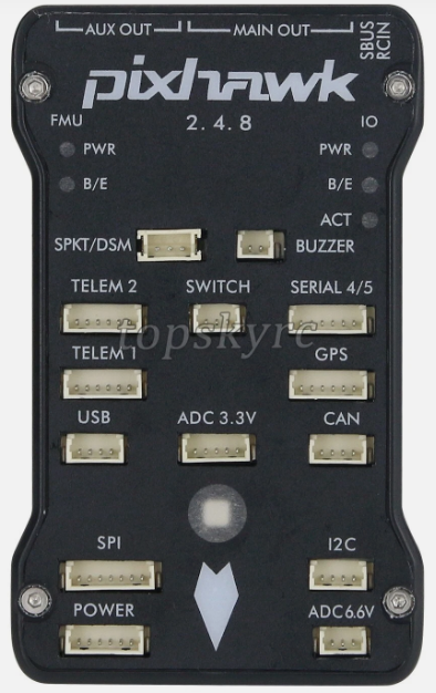
Pin Configuration and Descriptions

The PIXHAWK 2.4.8 features multiple connectors for peripherals and power. Below is a summary of the key pin configurations:

Power Input

Pin Name Description
Power (+) Positive voltage input (4.8V-5.4V)
Power (-) Ground connection

PWM/Servo Outputs

Pin Name Description
PWM1 - PWM14 Outputs for motor ESCs or servos
GND Ground connection

Communication Ports

Port Name Description
UART1 - UART5 Serial communication ports
I2C Interface for external sensors
SPI High-speed sensor interface
CAN Communication for UAVCAN devices

Auxiliary Ports

Port Name Description
ADC Analog-to-digital converter inputs
GPS GPS module connection
Telemetry 1/2 Telemetry data transmission

Usage Instructions

How to Use the PIXHAWK 2.4.8 in a Circuit

  1. Powering the Controller:

    • Connect a power module to the power input pins. Ensure the voltage is within the range of 4.8V to 5.4V.
    • Alternatively, power the controller via USB for configuration purposes.
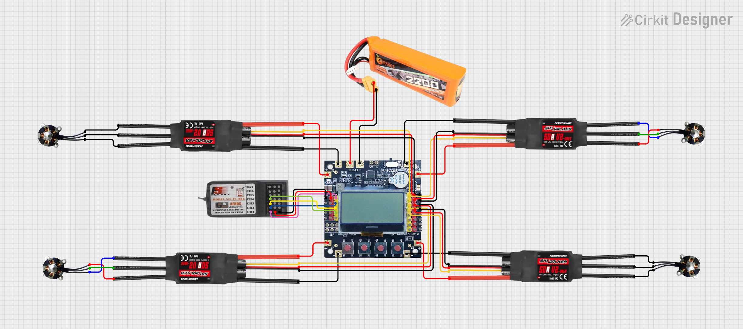
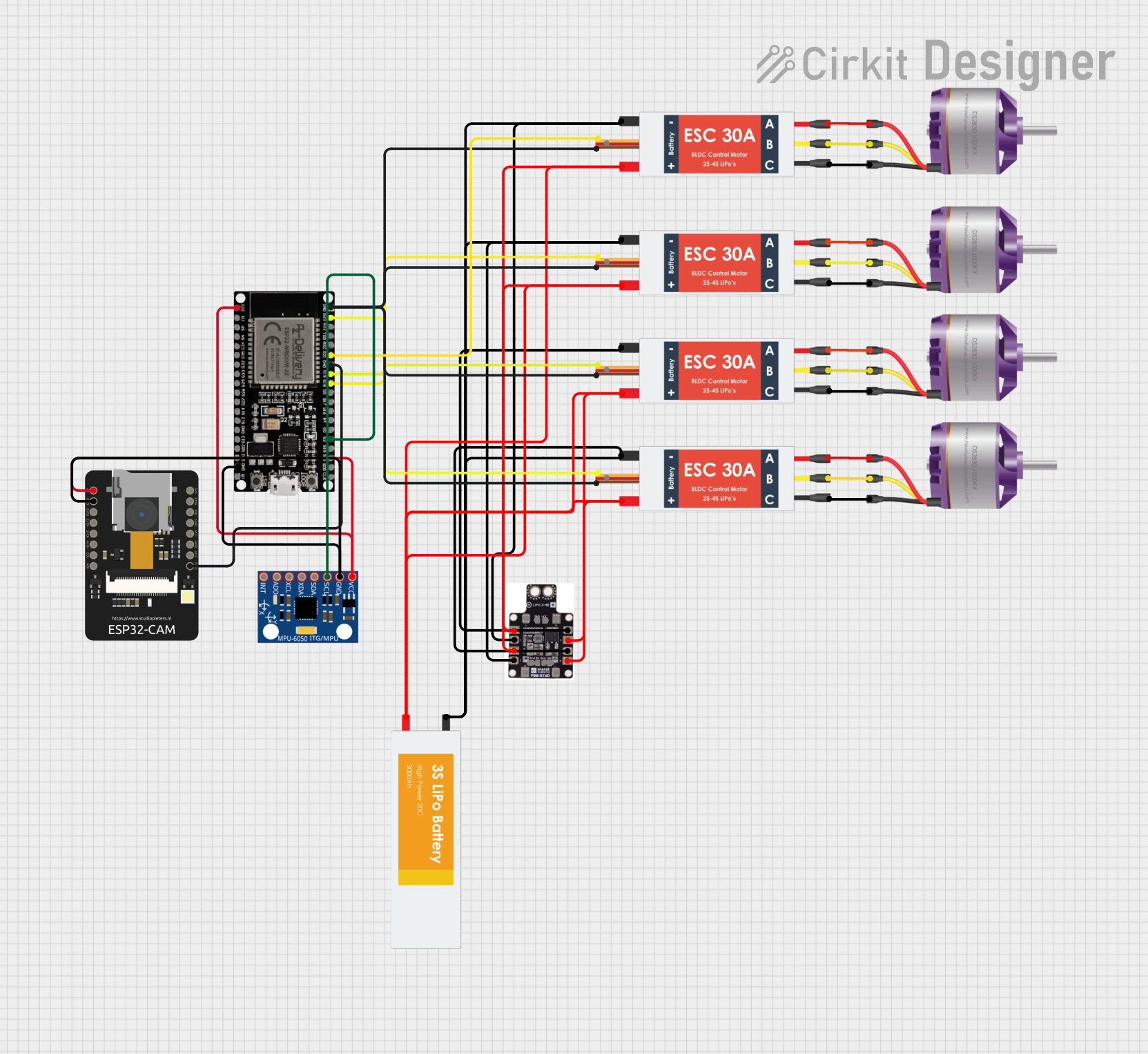
  2. Connecting Peripherals:

    • Attach ESCs or servos to the PWM output pins.
    • Connect sensors (e.g., GPS, barometer, or magnetometer) to the appropriate ports (I2C, SPI, or UART).
  3. Software Setup:

    • Install a compatible flight control software such as PX4 or ArduPilot.
    • Use a ground control station (e.g., QGroundControl or Mission Planner) to configure the controller.
  4. Calibrating Sensors:

    • Perform sensor calibration (e.g., accelerometer, gyroscope, and compass) using the ground control software.
    • Follow the on-screen instructions for proper calibration.
  5. Testing:

    • Conduct a pre-flight check to ensure all connections are secure and the system is functioning correctly.
    • Test motor outputs and verify sensor readings before flight.

Important Considerations and Best Practices

  • Always use a stable power source to avoid voltage fluctuations that may affect performance.
  • Ensure proper vibration damping for the controller to improve sensor accuracy.
  • Regularly update the firmware to benefit from the latest features and bug fixes.
  • Use a GPS module with a built-in compass for better navigation accuracy.
  • Perform a failsafe configuration to handle communication loss or low battery scenarios.

Example: Connecting to an Arduino UNO

The PIXHAWK 2.4.8 can communicate with an Arduino UNO via UART. Below is an example code snippet for reading telemetry data:

#include <SoftwareSerial.h>

// Define RX and TX pins for communication with PIXHAWK
SoftwareSerial pixhawkSerial(10, 11); // RX = pin 10, TX = pin 11

void setup() {
  // Initialize serial communication
  Serial.begin(9600); // For debugging via Serial Monitor
  pixhawkSerial.begin(57600); // Communication with PIXHAWK

  Serial.println("Starting communication with PIXHAWK...");
}

void loop() {
  // Check if data is available from PIXHAWK
  if (pixhawkSerial.available()) {
    // Read and print data from PIXHAWK
    char data = pixhawkSerial.read();
    Serial.print(data);
  }
}

Note: Ensure the UART port on the PIXHAWK is configured for telemetry output.

Troubleshooting and FAQs

Common Issues and Solutions

  1. Issue: The controller does not power on.

    • Solution: Verify the power module connection and ensure the input voltage is within the specified range (4.8V-5.4V).
  2. Issue: Motors do not respond to commands.

    • Solution: Check the PWM connections and ensure the ESCs are properly calibrated. Verify motor outputs in the ground control software.
  3. Issue: GPS module is not detected.

    • Solution: Ensure the GPS is connected to the correct port and the wiring is secure. Check the software configuration for GPS settings.
  4. Issue: Unstable flight or poor performance.

    • Solution: Perform sensor calibration and ensure proper vibration isolation. Verify the PID tuning parameters in the flight control software.

FAQs

  • Q: Can the PIXHAWK 2.4.8 be used with fixed-wing aircraft?

    • A: Yes, the controller supports fixed-wing, multirotor, and VTOL configurations.
  • Q: What software platforms are compatible with the PIXHAWK 2.4.8?

    • A: The controller is compatible with PX4, ArduPilot, and other open-source autopilot software.
  • Q: How do I update the firmware?

    • A: Use a ground control station like QGroundControl or Mission Planner to download and install the latest firmware.
  • Q: Is the PIXHAWK 2.4.8 waterproof?

    • A: No, the controller is not waterproof. Use a protective enclosure for outdoor applications in wet conditions.