Cirkit Designer Logo
Cirkit Designer
Your all-in-one circuit design IDE
Home / 
Component Documentation

How to Use YF-S201 Water Flow Meter: Examples, Pinouts, and Specs

Image of YF-S201 Water Flow Meter
Cirkit Designer LogoDesign with YF-S201 Water Flow Meter in Cirkit Designer

Introduction

The YF-S201 Water Flow Meter is a sensor designed to measure the flow rate of water through a pipe or hose. It operates by using a rotor that spins in response to water flow, with a hall-effect sensor that outputs a series of electrical pulses. These pulses can be counted to determine the volume of water that has passed through the meter. Common applications include irrigation systems, water conservation systems, and any application where water usage monitoring is necessary.

Explore Projects Built with YF-S201 Water Flow Meter

Use Cirkit Designer to design, explore, and prototype these projects online. Some projects support real-time simulation. Click "Open Project" to start designing instantly!
YF-S201 Water Flow Meter Interface with SN74AHCT125N Level Shifter
Image of Copy of flow: A project utilizing YF-S201 Water Flow Meter in a practical application
This circuit is designed to interface a YF-S201 Water Flow Meter with an SN74AHCT125N buffer/level shifter, likely for signal conditioning purposes. The power supply provides the necessary voltage to the flow meter, and decoupling capacitors are used to stabilize the buffer's power supply. The circuit is prepared for further expansion or connection to a microcontroller for data processing, although no microcontroller or its code is included in the provided information.
Cirkit Designer LogoOpen Project in Cirkit Designer
Arduino-Based Water Quality Monitoring System with SIM900A and Multiple Sensors
Image of feito: A project utilizing YF-S201 Water Flow Meter in a practical application
This circuit is a water quality monitoring system that uses an Arduino UNO to collect data from a YF-S201 water flow meter, a turbidity sensor, and a temperature sensor. The collected data is then transmitted via a SIM900A GSM module to a remote server or user through SMS. The system measures water flow rate, temperature, and turbidity, and sends periodic updates.
Cirkit Designer LogoOpen Project in Cirkit Designer
Arduino UNO-Based Water Flow and Temperature Monitoring System with LCD Display
Image of flow & temp: A project utilizing YF-S201 Water Flow Meter in a practical application
This circuit is a monitoring system that uses an Arduino UNO to measure water flow and temperature. It utilizes a YF-S201 water flow meter and a DS18B20 temperature sensor to collect data, which is then displayed on a 16x2 I2C LCD. The Arduino processes the sensor data and updates the display in real-time.
Cirkit Designer LogoOpen Project in Cirkit Designer
ESP32-Based Water Flow Monitoring System with OLED Display
Image of Smart Flow Metre: A project utilizing YF-S201 Water Flow Meter in a practical application
This circuit features an ESP32 microcontroller connected to a YF-S201 Water Flow Meter and a 0.96" OLED display. The ESP32 reads the flow rate data from the water flow meter via a digital input (D15) and communicates with the OLED display over I2C (D21 for SCK and D23 for SDA) to display the flow information. The Breadboard Power Module supplies power to the ESP32, the water flow meter, and the OLED display.
Cirkit Designer LogoOpen Project in Cirkit Designer

Explore Projects Built with YF-S201 Water Flow Meter

Use Cirkit Designer to design, explore, and prototype these projects online. Some projects support real-time simulation. Click "Open Project" to start designing instantly!
Image of Copy of flow: A project utilizing YF-S201 Water Flow Meter in a practical application
YF-S201 Water Flow Meter Interface with SN74AHCT125N Level Shifter
This circuit is designed to interface a YF-S201 Water Flow Meter with an SN74AHCT125N buffer/level shifter, likely for signal conditioning purposes. The power supply provides the necessary voltage to the flow meter, and decoupling capacitors are used to stabilize the buffer's power supply. The circuit is prepared for further expansion or connection to a microcontroller for data processing, although no microcontroller or its code is included in the provided information.
Cirkit Designer LogoOpen Project in Cirkit Designer
Image of feito: A project utilizing YF-S201 Water Flow Meter in a practical application
Arduino-Based Water Quality Monitoring System with SIM900A and Multiple Sensors
This circuit is a water quality monitoring system that uses an Arduino UNO to collect data from a YF-S201 water flow meter, a turbidity sensor, and a temperature sensor. The collected data is then transmitted via a SIM900A GSM module to a remote server or user through SMS. The system measures water flow rate, temperature, and turbidity, and sends periodic updates.
Cirkit Designer LogoOpen Project in Cirkit Designer
Image of flow & temp: A project utilizing YF-S201 Water Flow Meter in a practical application
Arduino UNO-Based Water Flow and Temperature Monitoring System with LCD Display
This circuit is a monitoring system that uses an Arduino UNO to measure water flow and temperature. It utilizes a YF-S201 water flow meter and a DS18B20 temperature sensor to collect data, which is then displayed on a 16x2 I2C LCD. The Arduino processes the sensor data and updates the display in real-time.
Cirkit Designer LogoOpen Project in Cirkit Designer
Image of Smart Flow Metre: A project utilizing YF-S201 Water Flow Meter in a practical application
ESP32-Based Water Flow Monitoring System with OLED Display
This circuit features an ESP32 microcontroller connected to a YF-S201 Water Flow Meter and a 0.96" OLED display. The ESP32 reads the flow rate data from the water flow meter via a digital input (D15) and communicates with the OLED display over I2C (D21 for SCK and D23 for SDA) to display the flow information. The Breadboard Power Module supplies power to the ESP32, the water flow meter, and the OLED display.
Cirkit Designer LogoOpen Project in Cirkit Designer

Technical Specifications

Key Technical Details

  • Operating Voltage: 5 to 18 VDC
  • Max Current: 15 mA (at 5 V)
  • Flow Rate Range: 1 to 30 liters per minute
  • Working Water Pressure: ≤ 1.75 MPa
  • Operating Temperature Range: ≤ 80°C
  • Accuracy: ±5%
  • Output Pulse High Level: > 4.5 VDC (input voltage 5 VDC)
  • Output Pulse Low Level: < 0.5 VDC (input voltage 5 VDC)
  • Output Pulse Duty Cycle: 50% ±10%

Pin Configuration and Descriptions

Pin Number Description Notes
1 GND (Ground) Connect to system ground
2 Signal Output (Pulse) Connect to a digital input pin
3 VCC (Power Supply) Connect to 5-18 VDC

Usage Instructions

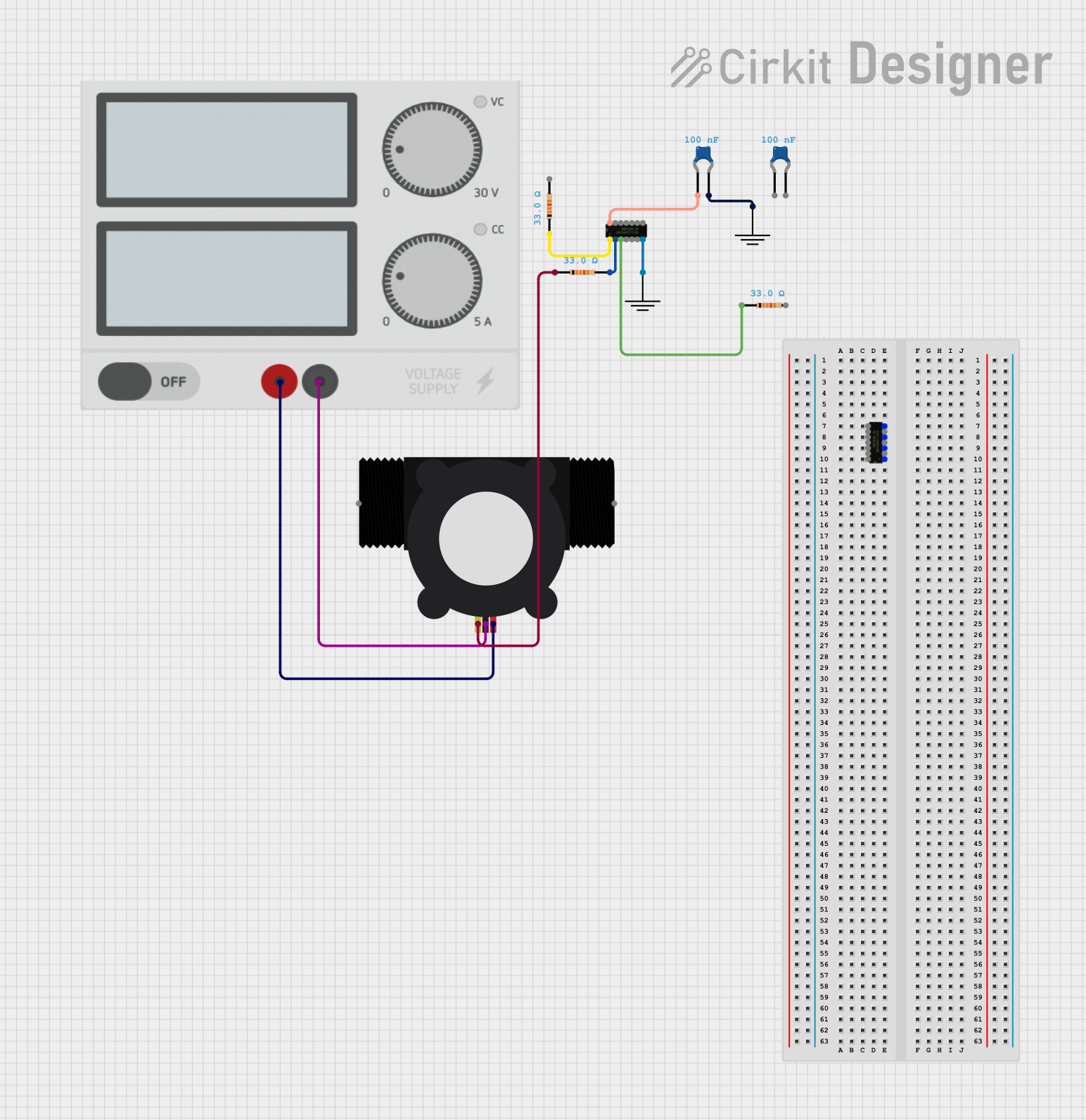
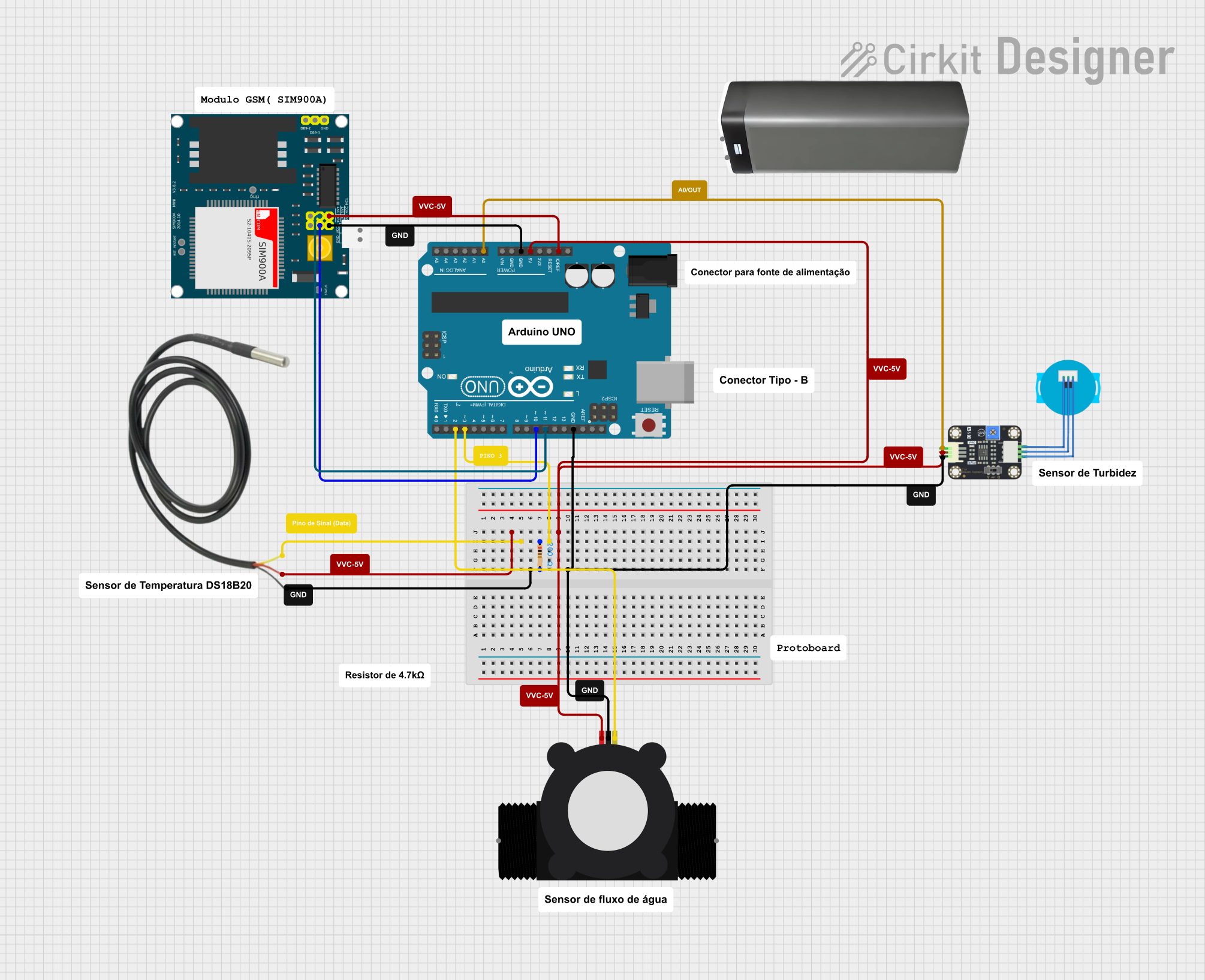
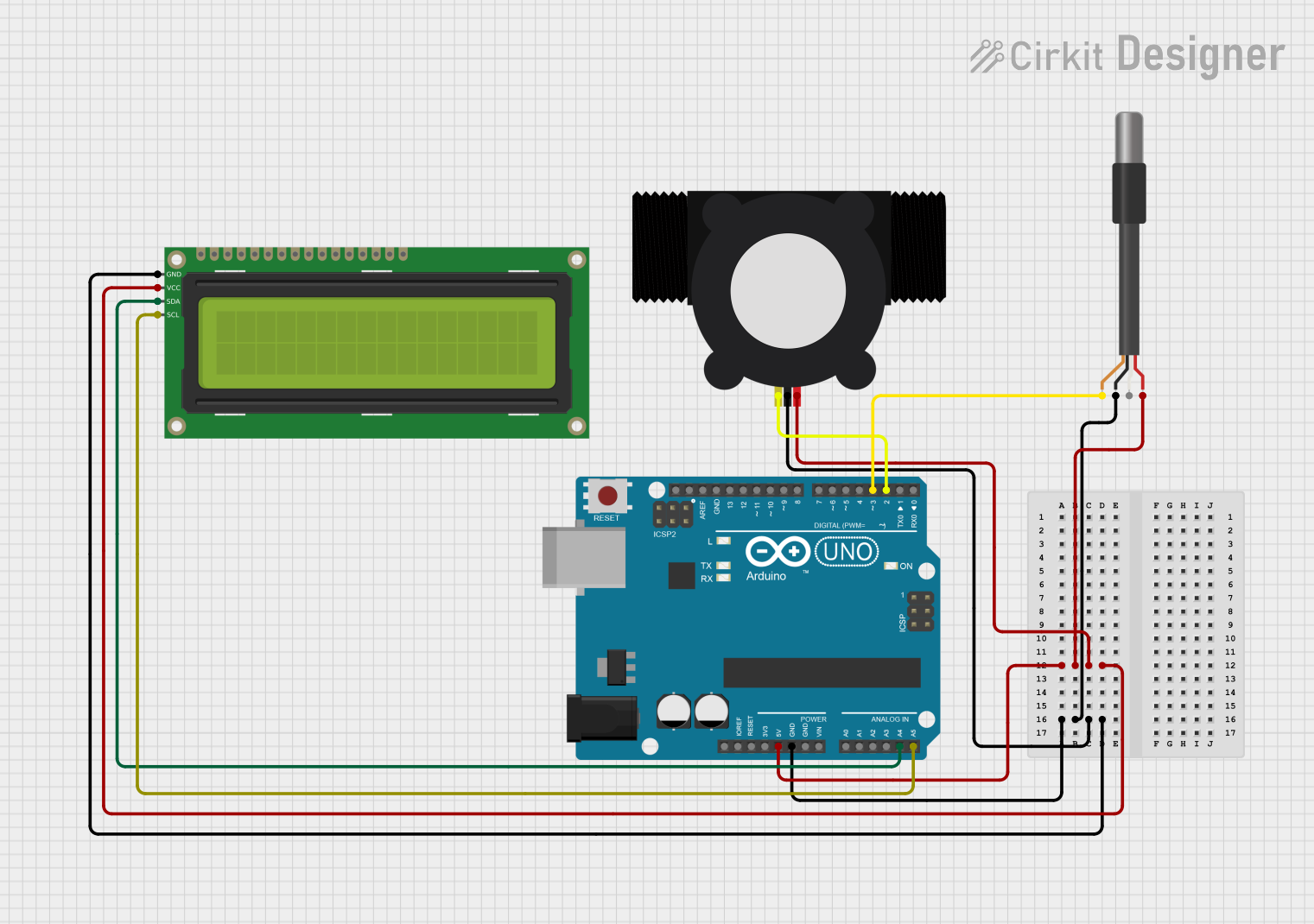
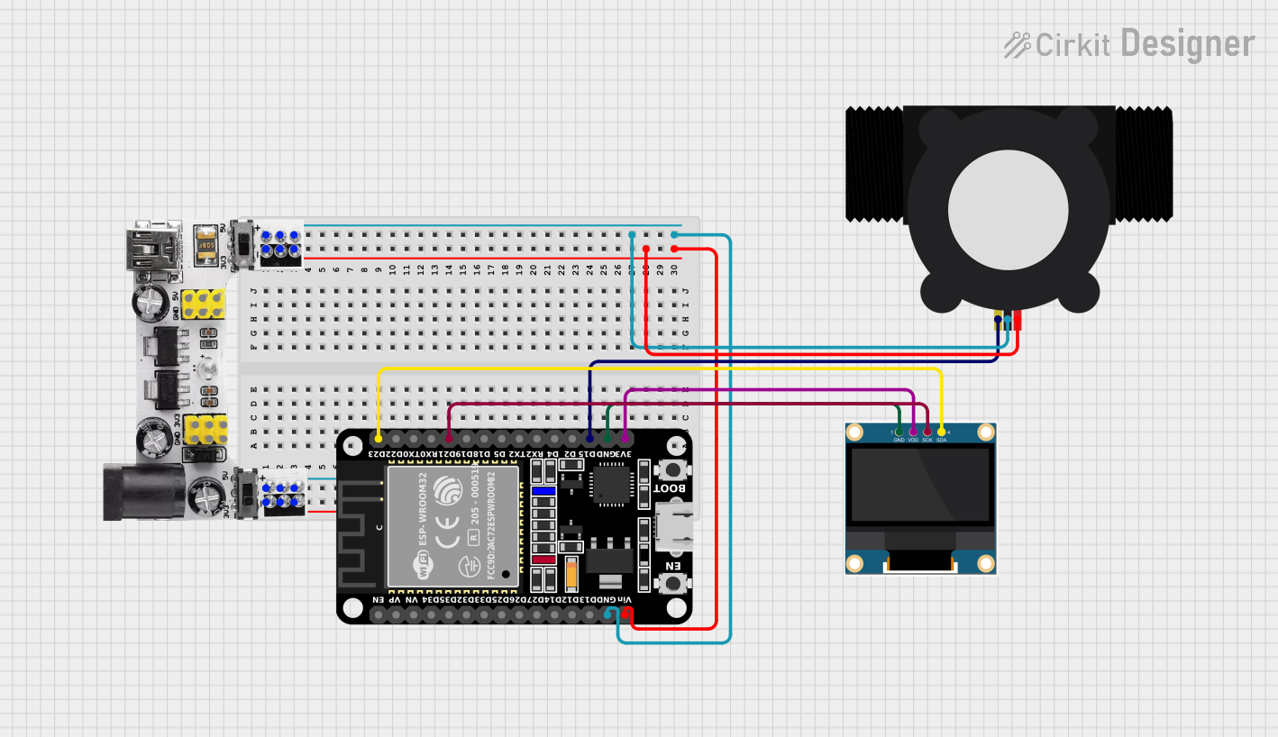
Integration with a Circuit

  1. Connect the VCC pin to a 5-18 VDC power supply.
  2. Connect the GND pin to the ground of the power supply.
  3. Connect the Signal Output pin to a digital input pin on a microcontroller, such as an Arduino UNO.

Important Considerations and Best Practices

  • Ensure that the water flow direction matches the arrow on the sensor.
  • Avoid subjecting the sensor to water pressure beyond its maximum rating.
  • Use a pull-up resistor if the microcontroller's input pin does not have an internal pull-up feature.
  • Filter the sensor's output signal to debounce the pulses if necessary.
  • Calibrate the sensor by measuring a known volume of water and adjusting the pulse count accordingly.

Example Code for Arduino UNO

// Define the pin connected to the flow meter
const int flowPin = 2;
volatile int flowPulseCount; // Volatile because it's changed in an interrupt

void setup() {
  Serial.begin(9600);
  pinMode(flowPin, INPUT);
  attachInterrupt(digitalPinToInterrupt(flowPin), pulseCounter, RISING); // Interrupt on rising edge of pulse
}

void loop() {
  // Disable the interrupt while calculating flow rate and volume to prevent errors
  noInterrupts();
  int flowRate = flowPulseCount;
  flowPulseCount = 0; // Reset pulse count after reading
  interrupts();

  // Calculate the flow rate in liters per minute (L/min)
  // The factor 7.5 is calibration factor, adjust as necessary for your specific sensor
  float flowRateLpm = (flowRate / 7.5);
  Serial.print("Flow rate: ");
  Serial.print(flowRateLpm);
  Serial.println(" L/min");

  // Delay for a second to get a stable reading
  delay(1000);
}

// Interrupt service routine to count pulses from the flow meter
void pulseCounter() {
  flowPulseCount++;
}

Troubleshooting and FAQs

Common Issues

  • No pulse output: Ensure the power supply is connected correctly and within the specified voltage range. Check for any loose connections.
  • Inaccurate readings: Verify that the water flow direction is correct. Calibrate the sensor as needed. Ensure there are no air bubbles in the line.
  • Erratic readings: Debounce the signal output or use a low-pass filter to smooth out the signal.

Solutions and Tips

  • Calibration: To calibrate the flow meter, measure a known volume of water and compare it to the pulse count. Adjust the calibration factor in the code accordingly.
  • Signal Debouncing: Implement a software debounce in the interrupt service routine or use a hardware filter.

FAQs

Q: Can the YF-S201 be used with hot water? A: The YF-S201 can be used with water up to 80°C. Beyond this temperature, the sensor may be damaged.

Q: How can I increase the accuracy of the sensor? A: Regular calibration and ensuring a full water pipe (no air) will help increase accuracy. Also, maintaining a steady flow rate during measurements is important.

Q: Is the YF-S201 Water Flow Meter food safe? A: The YF-S201 is not certified as food safe. It is intended for water measurement applications where food safety is not a concern.

Q: What is the lifespan of the YF-S201? A: The lifespan depends on usage conditions but it is generally designed for long-term use in typical water flow measurement applications. Regular maintenance and avoiding excessive water pressure can extend its lifespan.