How to Use DC-DC Step-down Buck Converter 5A - 5.5-32V to 3.3V output: Examples, Pinouts, and Specs
Introduction
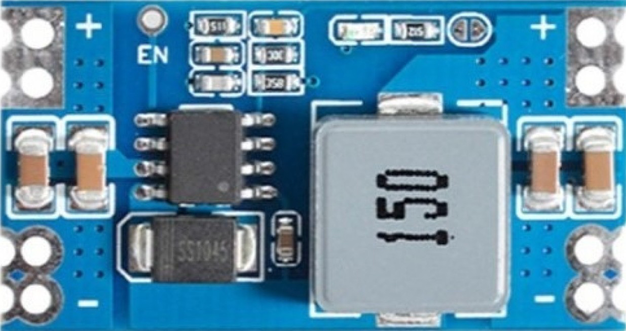
The DC-DC Step-down Buck Converter Mini 560 PRO 3.3V by Tinytronics is a high-efficiency voltage regulator designed to step down input voltages ranging from 5.5V to 32V to a stable 3.3V output. With a maximum output current of 5A, this converter is ideal for powering low-voltage devices such as microcontrollers, sensors, and other 3.3V electronics from higher voltage sources like batteries or power supplies.
Explore Projects Built with DC-DC Step-down Buck Converter 5A - 5.5-32V to 3.3V output


Explore Projects Built with DC-DC Step-down Buck Converter 5A - 5.5-32V to 3.3V output
Common Applications and Use Cases
- Powering 3.3V microcontrollers (e.g., ESP32, ESP8266) from 12V or 24V sources.
- Supplying stable 3.3V power to sensors, modules, and communication devices.
- Converting higher voltage battery packs (e.g., 2S-6S LiPo) to 3.3V for embedded systems.
- General-purpose voltage regulation in DIY electronics projects.
Technical Specifications
Key Technical Details
| Parameter | Value |
|---|---|
| Manufacturer | Tinytronics |
| Part ID | Mini 560 PRO 3.3V |
| Input Voltage Range | 5.5V to 32V |
| Output Voltage | 3.3V (fixed) |
| Maximum Output Current | 5A |
| Efficiency | Up to 95% |
| Switching Frequency | 150 kHz |
| Operating Temperature | -40°C to +85°C |
| Dimensions | 22mm x 17mm x 4mm |
Pin Configuration and Descriptions
| Pin Name | Description |
|---|---|
| VIN+ | Positive input voltage (5.5V to 32V). Connect to the positive terminal of the power source. |
| VIN- | Negative input voltage (GND). Connect to the ground of the power source. |
| VOUT+ | Positive output voltage (3.3V). Connect to the load's positive terminal. |
| VOUT- | Negative output voltage (GND). Connect to the load's ground terminal. |
Usage Instructions
How to Use the Component in a Circuit
Connect the Input Voltage:
- Attach the positive terminal of your power source (5.5V to 32V) to the
VIN+pin. - Connect the ground terminal of your power source to the
VIN-pin.
- Attach the positive terminal of your power source (5.5V to 32V) to the
Connect the Output Voltage:
- Connect the
VOUT+pin to the positive terminal of your load (e.g., microcontroller, sensor). - Connect the
VOUT-pin to the ground terminal of your load.
- Connect the
Verify Connections:
- Double-check all connections to ensure proper polarity and avoid short circuits.
Power On:
- Turn on the power source. The converter will regulate the input voltage to a stable 3.3V output.
Important Considerations and Best Practices
- Input Voltage Range: Ensure the input voltage is within the specified range (5.5V to 32V). Exceeding this range may damage the converter.
- Heat Dissipation: At higher currents (e.g., 5A), the converter may generate heat. Use proper ventilation or a heatsink if necessary.
- Load Requirements: Ensure the load does not exceed the maximum output current of 5A.
- Polarity Protection: Double-check the polarity of the input and output connections to avoid damage to the converter or connected devices.
Example: Using with an Arduino UNO
While the Arduino UNO operates at 5V, you can use the Mini 560 PRO 3.3V to power 3.3V peripherals connected to the Arduino. Below is an example of connecting a 3.3V sensor to the Arduino using the buck converter.
Circuit Diagram
- Connect the Mini 560 PRO's
VIN+andVIN-to a 12V power source. - Connect the Mini 560 PRO's
VOUT+andVOUT-to the sensor's power pins. - Connect the sensor's data pin to the Arduino's input pin.
Example Arduino Code
// Example code to read data from a 3.3V sensor connected via the Mini 560 PRO
// Ensure the sensor's data pin is connected to Arduino pin A0

const int sensorPin = A0; // Analog pin connected to the sensor
int sensorValue = 0;      // Variable to store the sensor reading

void setup() {
  Serial.begin(9600); // Initialize serial communication at 9600 baud
  pinMode(sensorPin, INPUT); // Set the sensor pin as input
}

void loop() {
  sensorValue = analogRead(sensorPin); // Read the sensor value
  Serial.print("Sensor Value: ");
  Serial.println(sensorValue); // Print the sensor value to the Serial Monitor
  delay(1000); // Wait for 1 second before the next reading
}
Troubleshooting and FAQs
Common Issues and Solutions
| Issue | Possible Cause | Solution |
|---|---|---|
| No output voltage | Incorrect input connections | Verify VIN+ and VIN- connections. |
| Output voltage is unstable | Input voltage is too low or noisy | Ensure input voltage is within range and use a capacitor to filter noise. |
| Converter overheats | Excessive load current | Reduce the load or improve heat dissipation with a heatsink. |
| Connected device not working | Load exceeds 5A or incorrect wiring | Check load current and verify wiring. |
FAQs
Can I adjust the output voltage?
- No, the Mini 560 PRO 3.3V has a fixed output voltage of 3.3V.
What happens if I exceed the input voltage range?
- Exceeding the input voltage range (5.5V to 32V) may permanently damage the converter.
Can I use this converter with a battery?
- Yes, it is compatible with battery sources as long as the voltage is within the specified range.
Is reverse polarity protection included?
- No, the Mini 560 PRO does not have built-in reverse polarity protection. Ensure correct polarity during installation.
This concludes the documentation for the DC-DC Step-down Buck Converter Mini 560 PRO 3.3V. For further assistance, refer to the manufacturer's datasheet or contact Tinytronics support.