How to Use 40 AMP DC Breaker: Examples, Pinouts, and Specs
Introduction
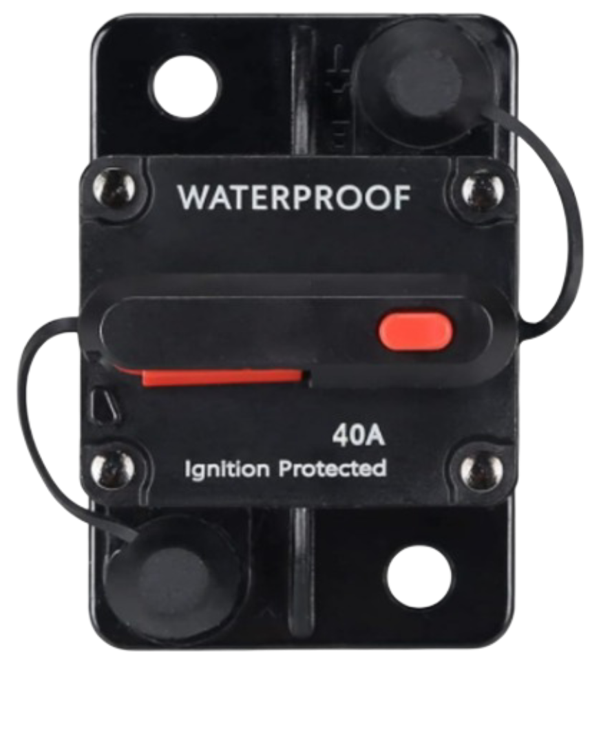
The 40 AMP DC Breaker is a protective device designed to interrupt the flow of direct current (DC) in a circuit when the current exceeds 40 amps. This ensures the safety of electrical components and prevents potential damage caused by overcurrent conditions. The breaker is an essential component in DC power systems, offering reliable protection and easy reset functionality.
Explore Projects Built with 40 AMP DC Breaker
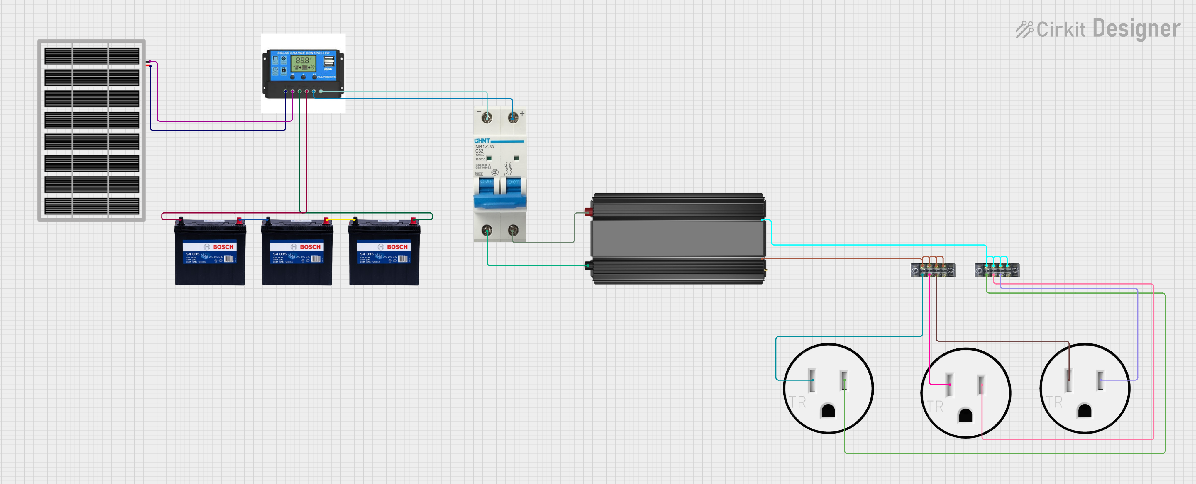
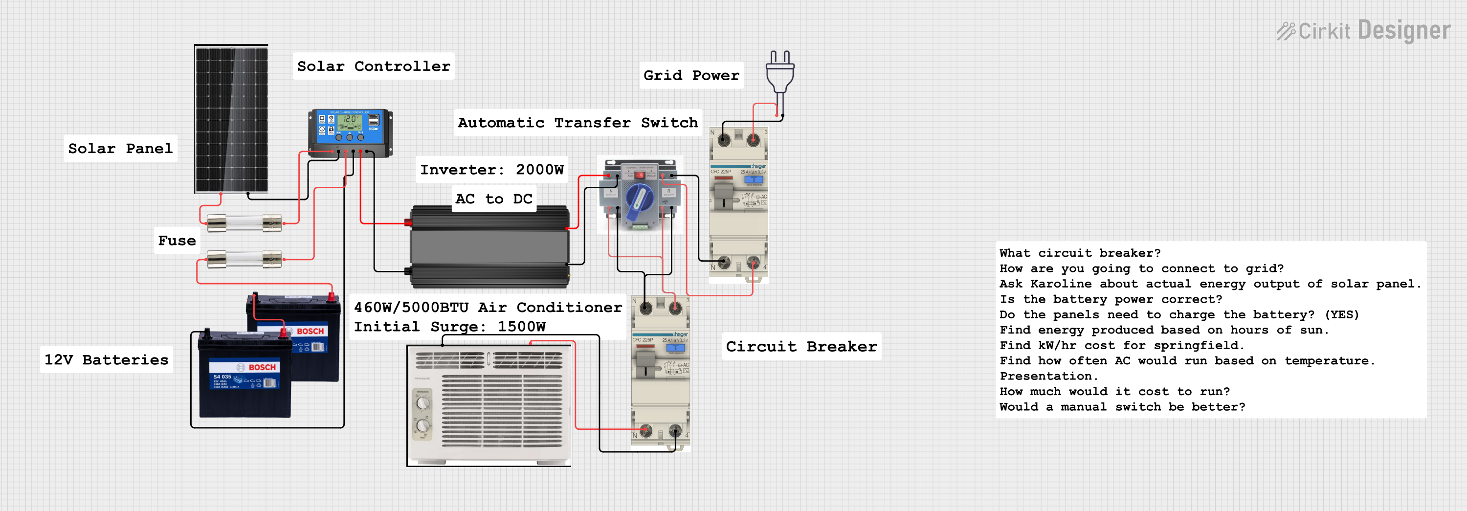

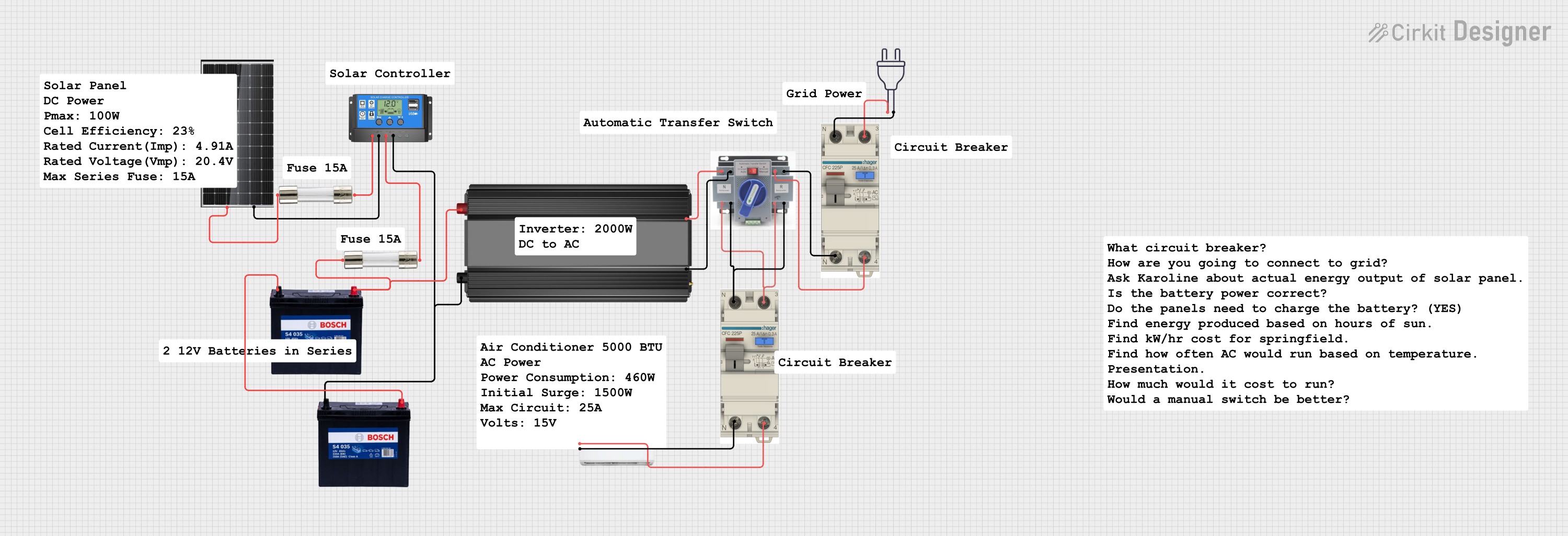
Explore Projects Built with 40 AMP DC Breaker
Common Applications and Use Cases
- Solar power systems to protect batteries and inverters
- Electric vehicle (EV) charging stations
- DC motor protection in industrial applications
- Marine and RV electrical systems
- Backup power systems and uninterruptible power supplies (UPS)
Technical Specifications
The following table outlines the key technical details of the 40 AMP DC Breaker:
| Parameter | Value |
|---|---|
| Rated Current | 40 Amps |
| Rated Voltage | 12V DC, 24V DC, or 48V DC |
| Interrupting Capacity | 5,000 Amps @ 48V DC |
| Operating Temperature | -20°C to 60°C |
| Mounting Type | Panel mount or surface mount |
| Reset Type | Manual reset |
| Dimensions | Varies by model (e.g., 80x50x30 mm) |
| Compliance Standards | UL 1077, CE, RoHS |
Pin Configuration and Descriptions
The 40 AMP DC Breaker typically has two terminals for electrical connections. The table below describes the terminals:
| Terminal | Description |
|---|---|
| Line (Input) | Connects to the power source (positive DC terminal). |
| Load (Output) | Connects to the load or circuit being protected. |
Usage Instructions
How to Use the Component in a Circuit
- Determine the Voltage and Current Requirements: Ensure the breaker is rated for the voltage and current of your DC circuit (e.g., 12V, 24V, or 48V DC with a maximum of 40 amps).
- Connect the Terminals:
- Connect the Line (Input) terminal to the positive terminal of the DC power source.
- Connect the Load (Output) terminal to the positive terminal of the load or circuit.
- Secure the Breaker: Mount the breaker securely using the panel or surface mount option.
- Test the Circuit: Power on the system and verify that the breaker operates correctly under normal conditions.
Important Considerations and Best Practices
- Wire Gauge: Use appropriately rated wires for 40 amps to prevent overheating. For example, 8 AWG or thicker wires are recommended.
- Polarity: Ensure correct polarity when connecting the breaker to avoid damage.
- Environmental Conditions: Install the breaker in a dry, well-ventilated area to prevent moisture or dust from affecting its performance.
- Resetting the Breaker: In the event of a trip, identify and resolve the cause of the overcurrent before manually resetting the breaker.
Example: Connecting to an Arduino UNO
While the 40 AMP DC Breaker is not directly connected to an Arduino UNO, it can be used in circuits powered by an Arduino. For example, in a motor control project, the breaker can protect the motor driver and power supply. Below is an example Arduino code for controlling a DC motor:
// Example Arduino code for controlling a DC motor with a breaker in the circuit

const int motorPin = 9; // PWM pin connected to motor driver input

void setup() {
  pinMode(motorPin, OUTPUT); // Set motor pin as output
}

void loop() {
  analogWrite(motorPin, 128); // Run motor at 50% speed
  delay(5000); // Run for 5 seconds

  analogWrite(motorPin, 0); // Stop motor
  delay(2000); // Wait for 2 seconds
}
Note: Ensure the 40 AMP DC Breaker is installed between the power source and the motor driver to protect the circuit from overcurrent.
Troubleshooting and FAQs
Common Issues Users Might Face
Breaker Trips Frequently:
- Cause: The load exceeds 40 amps or there is a short circuit.
- Solution: Check the load current and ensure it is within the breaker's rating. Inspect the circuit for shorts.
Breaker Does Not Reset:
- Cause: The overcurrent condition has not been resolved, or the breaker is damaged.
- Solution: Verify the circuit is safe and free of faults before attempting to reset. Replace the breaker if it is faulty.
Breaker Overheats:
- Cause: Loose connections or undersized wires.
- Solution: Tighten all connections and use wires rated for 40 amps or higher.
Solutions and Tips for Troubleshooting
- Inspect Connections: Ensure all terminals are securely fastened and free of corrosion.
- Check Load Ratings: Verify that the connected load does not exceed the breaker's rated current.
- Test the Breaker: Use a multimeter to check continuity across the terminals when the breaker is in the "ON" position.
By following these guidelines, the 40 AMP DC Breaker can provide reliable protection for your DC circuits, ensuring safety and longevity for your electrical systems.