How to Use 10A High Efficiency Automatic Step UP - Down Dc-Dc converter: Examples, Pinouts, and Specs
Introduction
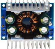
The 10A High Efficiency Automatic Step Up - Down DC-DC Converter is a versatile power management component designed to automatically adjust voltage levels. It can step up or step down the input voltage to provide a stable output voltage, making it ideal for applications requiring efficient power conversion. With a maximum output current of 10A, this converter is suitable for powering devices with varying voltage requirements.
Explore Projects Built with 10A High Efficiency Automatic Step UP - Down Dc-Dc converter


Explore Projects Built with 10A High Efficiency Automatic Step UP - Down Dc-Dc converter
Common Applications and Use Cases
- Powering microcontrollers, such as Arduino UNO, and other development boards.
- Battery-powered systems requiring stable voltage output.
- Robotics and motor control applications.
- LED lighting systems.
- Renewable energy systems, such as solar panels.
- Portable electronics and USB power banks.
Technical Specifications
The following table outlines the key technical details of the 10A High Efficiency Automatic Step Up - Down DC-DC Converter:
| Parameter | Specification |
|---|---|
| Input Voltage Range | 5V to 30V |
| Output Voltage Range | 1.25V to 30V (adjustable) |
| Maximum Output Current | 10A |
| Efficiency | Up to 95% (depending on input/output ratio) |
| Switching Frequency | 150 kHz |
| Operating Temperature | -40°C to +85°C |
| Dimensions | 60mm x 50mm x 20mm |
Pin Configuration and Descriptions
The converter has the following pin configuration:
| Pin Name | Description |
|---|---|
| VIN+ | Positive input voltage terminal (5V to 30V). |
| VIN- | Negative input voltage terminal (GND). |
| VOUT+ | Positive output voltage terminal (1.25V to 30V). |
| VOUT- | Negative output voltage terminal (GND). |
| ADJ | Voltage adjustment pin (use a potentiometer or resistor). |
Usage Instructions
How to Use the Component in a Circuit
Connect Input Voltage:
- Connect the positive terminal of your power source to the
VIN+pin. - Connect the negative terminal of your power source to the
VIN-pin.
- Connect the positive terminal of your power source to the
Connect Output Load:
- Connect the positive terminal of your load to the
VOUT+pin. - Connect the negative terminal of your load to the
VOUT-pin.
- Connect the positive terminal of your load to the
Adjust Output Voltage:
- Use the
ADJpin to set the desired output voltage. This can be done by turning the onboard potentiometer or connecting an external resistor.
- Use the
Verify Connections:
- Double-check all connections to ensure proper polarity and secure wiring.
Power On:
- Turn on the power source and measure the output voltage using a multimeter to confirm the desired voltage level.
Important Considerations and Best Practices
- Ensure the input voltage is within the specified range (5V to 30V).
- Do not exceed the maximum output current of 10A to avoid damage.
- Use proper heat dissipation methods (e.g., heatsinks or fans) if operating at high currents.
- Avoid short circuits between the input and output terminals.
- For Arduino UNO or other microcontroller applications, ensure the output voltage matches the required operating voltage (e.g., 5V or 3.3V).
Example: Connecting to an Arduino UNO
To power an Arduino UNO using the converter:
- Set the output voltage to 5V using the
ADJpin. - Connect the
VOUT+pin to the Arduino's 5V pin. - Connect the
VOUT-pin to the Arduino's GND pin.
Here is an example Arduino code to test the setup:
// Example code to blink an LED connected to pin 13 on the Arduino UNO
// Ensure the DC-DC converter is providing a stable 5V to the Arduino UNO.

void setup() {
  pinMode(13, OUTPUT); // Set pin 13 as an output pin
}

void loop() {
  digitalWrite(13, HIGH); // Turn the LED on
  delay(1000);            // Wait for 1 second
  digitalWrite(13, LOW);  // Turn the LED off
  delay(1000);            // Wait for 1 second
}
Troubleshooting and FAQs
Common Issues and Solutions
No Output Voltage:
- Check the input voltage to ensure it is within the specified range.
- Verify all connections, especially the polarity of the input and output terminals.
- Ensure the
ADJpin is properly configured.
Overheating:
- Ensure adequate heat dissipation using heatsinks or fans.
- Reduce the load current if it exceeds the converter's capacity.
Fluctuating Output Voltage:
- Check for loose connections or poor soldering.
- Verify that the input voltage is stable and not dropping under load.
Arduino UNO Not Powering On:
- Confirm that the output voltage is set to 5V.
- Check the connections between the converter and the Arduino UNO.
FAQs
Q: Can this converter be used with a 12V battery?
A: Yes, the converter can step up or step down the voltage from a 12V battery to the desired output voltage within the range of 1.25V to 30V.
Q: Is the output voltage adjustable while the converter is operating?
A: Yes, the output voltage can be adjusted in real-time using the ADJ pin, but ensure the load is not sensitive to voltage fluctuations during adjustment.
Q: Can I use this converter to power multiple devices simultaneously?
A: Yes, as long as the total current draw does not exceed 10A and the output voltage is suitable for all connected devices.
Q: Does the converter have reverse polarity protection?
A: No, the converter does not have built-in reverse polarity protection. Ensure correct polarity to avoid damage.