How to Use E32: Examples, Pinouts, and Specs

 Design with E32 in Cirkit Designer
Introduction
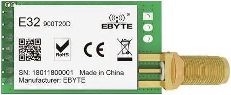
The E32-900T20D-V8 is a wireless communication module manufactured by LORA. It operates in the 2.4 GHz frequency range and is designed for long-range data transmission with low power consumption. This module is part of the E32 series and is widely used in IoT applications, enabling seamless wireless communication between devices. Its robust design and reliable performance make it suitable for industrial automation, smart agriculture, home automation, and other wireless data transmission applications.
Explore Projects Built with E32

 Open Project in Cirkit Designer
 Open Project in Cirkit Designer
 Open Project in Cirkit Designer
 Open Project in Cirkit Designer
Explore Projects Built with E32

 Open Project in Cirkit Designer
 Open Project in Cirkit Designer
 Open Project in Cirkit Designer
 Open Project in Cirkit Designer
Common Applications
- Internet of Things (IoT) devices
- Smart agriculture and environmental monitoring
- Home automation systems
- Industrial automation and control
- Wireless sensor networks
- Remote data logging and telemetry
Technical Specifications
Key Technical Details
| Parameter | Value |
|---|---|
| Operating Frequency | 2.4 GHz |
| Communication Protocol | LoRa |
| Transmission Power | 20 dBm (100 mW) |
| Sensitivity | -132 dBm |
| Data Rate | 0.3 kbps to 19.2 kbps |
| Operating Voltage | 2.3V to 5.5V |
| Current Consumption | 15 mA (Receive), 120 mA (Transmit) |
| Operating Temperature | -40°C to +85°C |
| Communication Interface | UART |
| Dimensions | 24 mm x 43 mm x 8 mm |
Pin Configuration and Descriptions
The E32-900T20D-V8 module has 8 pins. Below is the pin configuration:
| Pin Number | Pin Name | Description |
|---|---|---|
| 1 | M0 | Mode selection pin 0. Used to configure the module's operating mode. |
| 2 | M1 | Mode selection pin 1. Used in conjunction with M0 for mode configuration. |
| 3 | RXD | UART Receive pin. Connect to the TX pin of the microcontroller. |
| 4 | TXD | UART Transmit pin. Connect to the RX pin of the microcontroller. |
| 5 | AUX | Auxiliary pin. Indicates the module's working status. |
| 6 | VCC | Power supply pin. Accepts 2.3V to 5.5V. |
| 7 | GND | Ground pin. Connect to the ground of the power supply. |
| 8 | ANT | Antenna interface. Connect to an external antenna for wireless communication. |
Usage Instructions
How to Use the E32-900T20D-V8 in a Circuit
- Power Supply: Connect the VCC pin to a stable power source (2.3V to 5.5V) and the GND pin to the ground.
- UART Communication: Connect the RXD pin to the TX pin of the microcontroller and the TXD pin to the RX pin of the microcontroller.
- Mode Selection: Use the M0 and M1 pins to configure the module's operating mode:
- Mode 0 (Normal Mode): M0 = 0, M1 = 0
- Mode 1 (Wake-up Mode): M0 = 1, M1 = 0
- Mode 2 (Power-saving Mode): M0 = 0, M1 = 1
- Mode 3 (Sleep Mode): M0 = 1, M1 = 1
- Antenna Connection: Attach an external antenna to the ANT pin for optimal wireless communication.
- Status Monitoring: Use the AUX pin to monitor the module's status. It can indicate when the module is ready to transmit or receive data.
Important Considerations and Best Practices
- Use a high-quality antenna to maximize the communication range and signal strength.
- Ensure proper grounding to avoid noise interference.
- Avoid placing the module near high-frequency devices to reduce signal interference.
- Use appropriate pull-up or pull-down resistors on the M0 and M1 pins for stable mode selection.
- Configure the UART baud rate of the microcontroller to match the module's default baud rate (9600 bps by default).
Example: Connecting to an Arduino UNO
Below is an example of how to connect and use the E32-900T20D-V8 with an Arduino UNO:
Wiring Diagram
| E32 Pin | Arduino Pin |
|---|---|
| VCC | 5V |
| GND | GND |
| RXD | D3 |
| TXD | D2 |
| M0 | D4 |
| M1 | D5 |
| AUX | D6 |
Arduino Code
#include <SoftwareSerial.h>

// Define pins for SoftwareSerial
SoftwareSerial E32Serial(2, 3); // RX = Pin 2, TX = Pin 3

// Define mode selection pins
const int M0 = 4;
const int M1 = 5;
const int AUX = 6;

void setup() {
  // Initialize serial communication
  Serial.begin(9600); // For debugging
  E32Serial.begin(9600); // For E32 module communication

  // Configure mode selection pins
  pinMode(M0, OUTPUT);
  pinMode(M1, OUTPUT);
  pinMode(AUX, INPUT);

  // Set module to Normal Mode (M0 = 0, M1 = 0)
  digitalWrite(M0, LOW);
  digitalWrite(M1, LOW);

  Serial.println("E32 Module Initialized");
}

void loop() {
  // Send data to the E32 module
  if (Serial.available()) {
    String data = Serial.readString();
    E32Serial.println(data);
    Serial.println("Data sent to E32: " + data);
  }

  // Receive data from the E32 module
  if (E32Serial.available()) {
    String receivedData = E32Serial.readString();
    Serial.println("Data received from E32: " + receivedData);
  }
}
Troubleshooting and FAQs
Common Issues and Solutions
No Communication Between Devices
- Ensure the RXD and TXD pins are correctly connected to the microcontroller.
- Verify that the UART baud rate matches between the module and the microcontroller.
Short Communication Range
- Check the antenna connection and ensure it is securely attached.
- Avoid obstructions or interference from other devices operating in the 2.4 GHz range.
Module Not Responding
- Verify the power supply voltage is within the specified range (2.3V to 5.5V).
- Check the AUX pin to ensure the module is not in a busy state.
Incorrect Mode Configuration
- Double-check the M0 and M1 pin configurations for the desired operating mode.
- Use pull-up or pull-down resistors if the mode selection is unstable.
FAQs
Q: Can the E32-900T20D-V8 be used with 3.3V microcontrollers?
A: Yes, the module supports an operating voltage range of 2.3V to 5.5V, making it compatible with both 3.3V and 5V systems.
Q: What is the maximum communication range of the module?
A: The maximum range depends on the environment and antenna quality. In open areas, it can reach up to 1 km with a high-quality antenna.
Q: How do I reset the module to factory settings?
A: Send the appropriate AT command (AT+DEFAULT) via UART to reset the module to its default configuration.
Q: Can multiple E32 modules communicate with each other?
A: Yes, multiple modules can communicate in a network. Ensure they are configured with the same frequency, address, and channel settings.