Cirkit Designer Logo
Cirkit Designer
Your all-in-one circuit design IDE
Home / 
Component Documentation

How to Use WS2812 RGB LED matrix 5x8: Examples, Pinouts, and Specs

Image of WS2812 RGB LED matrix 5x8
Cirkit Designer LogoDesign with WS2812 RGB LED matrix 5x8 in Cirkit Designer

Introduction

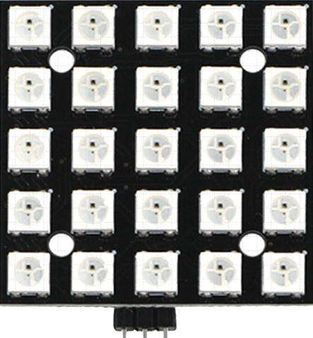
The WS2812 RGB LED Matrix 5x8 (Manufacturer Part ID: WS2812B-25P) by Adafruit is a compact and versatile LED matrix consisting of 40 individually addressable RGB LEDs arranged in a 5x8 grid. Each LED is capable of producing 24-bit color, allowing for vibrant and dynamic displays. The matrix is controlled via a single data line, making it easy to integrate into microcontroller-based projects.

Explore Projects Built with WS2812 RGB LED matrix 5x8

Use Cirkit Designer to design, explore, and prototype these projects online. Some projects support real-time simulation. Click "Open Project" to start designing instantly!
ESP32-Controlled WS2812 LED Matrix Display with Resistor
Image of esp32 door sign project: A project utilizing WS2812 RGB LED matrix 5x8 in a practical application
This circuit features an ESP32 microcontroller connected to a 32x8 WS2812 LED matrix. The ESP32 controls the LED matrix through a 220-ohm resistor connected to its D12 pin, providing data input to the matrix, while power and ground connections are shared between the ESP32 and the LED matrix.
Cirkit Designer LogoOpen Project in Cirkit Designer
Arduino-Controlled Dual WS2812 RGB LED Matrix Eye Animation Display
Image of eye project: A project utilizing WS2812 RGB LED matrix 5x8 in a practical application
This circuit consists of an Arduino UNO microcontroller connected to two daisy-chained WS2812 RGB LED 8x8 matrices. The Arduino controls the LED matrices to display patterns that simulate a slow blinking human eyes effect. The code for the Arduino is written to create and cycle through different eye patterns, varying from open to half-closed to closed, to achieve the blinking effect.
Cirkit Designer LogoOpen Project in Cirkit Designer
Arduino UNO Controlled RGB LED Matrix with Bluetooth Connectivity and Audio Output
Image of the bell : A project utilizing WS2812 RGB LED matrix 5x8 in a practical application
This is an interactive display and communication circuit. It uses an Arduino UNO to drive multiple WS2812 RGB LED matrices for visual output, interfaces with a DS3231 RTC for time-related functions, and communicates wirelessly via an HC-05 Bluetooth module. Additionally, it features audio output capabilities through a speaker connected to a PAM8403 audio amplifier.
Cirkit Designer LogoOpen Project in Cirkit Designer
ESP8266 NodeMCU Controlled 8x8 LED Matrix Display
Image of Nodemcu: A project utilizing WS2812 RGB LED matrix 5x8 in a practical application
This circuit connects an ESP8266 NodeMCU microcontroller to an 8x8 LED matrix display. The NodeMCU controls the matrix using digital pins D5, D7, and D8 for chip select (CS), data input (DIN), and clock (CLK) signals, respectively. The circuit is designed to display patterns or characters on the LED matrix, which are driven by the microcontroller.
Cirkit Designer LogoOpen Project in Cirkit Designer

Explore Projects Built with WS2812 RGB LED matrix 5x8

Use Cirkit Designer to design, explore, and prototype these projects online. Some projects support real-time simulation. Click "Open Project" to start designing instantly!
Image of esp32 door sign project: A project utilizing WS2812 RGB LED matrix 5x8 in a practical application
ESP32-Controlled WS2812 LED Matrix Display with Resistor
This circuit features an ESP32 microcontroller connected to a 32x8 WS2812 LED matrix. The ESP32 controls the LED matrix through a 220-ohm resistor connected to its D12 pin, providing data input to the matrix, while power and ground connections are shared between the ESP32 and the LED matrix.
Cirkit Designer LogoOpen Project in Cirkit Designer
Image of eye project: A project utilizing WS2812 RGB LED matrix 5x8 in a practical application
Arduino-Controlled Dual WS2812 RGB LED Matrix Eye Animation Display
This circuit consists of an Arduino UNO microcontroller connected to two daisy-chained WS2812 RGB LED 8x8 matrices. The Arduino controls the LED matrices to display patterns that simulate a slow blinking human eyes effect. The code for the Arduino is written to create and cycle through different eye patterns, varying from open to half-closed to closed, to achieve the blinking effect.
Cirkit Designer LogoOpen Project in Cirkit Designer
Image of the bell : A project utilizing WS2812 RGB LED matrix 5x8 in a practical application
Arduino UNO Controlled RGB LED Matrix with Bluetooth Connectivity and Audio Output
This is an interactive display and communication circuit. It uses an Arduino UNO to drive multiple WS2812 RGB LED matrices for visual output, interfaces with a DS3231 RTC for time-related functions, and communicates wirelessly via an HC-05 Bluetooth module. Additionally, it features audio output capabilities through a speaker connected to a PAM8403 audio amplifier.
Cirkit Designer LogoOpen Project in Cirkit Designer
Image of Nodemcu: A project utilizing WS2812 RGB LED matrix 5x8 in a practical application
ESP8266 NodeMCU Controlled 8x8 LED Matrix Display
This circuit connects an ESP8266 NodeMCU microcontroller to an 8x8 LED matrix display. The NodeMCU controls the matrix using digital pins D5, D7, and D8 for chip select (CS), data input (DIN), and clock (CLK) signals, respectively. The circuit is designed to display patterns or characters on the LED matrix, which are driven by the microcontroller.
Cirkit Designer LogoOpen Project in Cirkit Designer

Common Applications

  • Animated text and graphics displays
  • Wearable electronics and costumes
  • Mood lighting and decorative installations
  • Status indicators and dashboards
  • Educational projects and prototyping

Technical Specifications

Key Technical Details

Parameter Value
Manufacturer Adafruit
Part ID WS2812B-25P
LED Count 40 LEDs (5x8 grid)
LED Type WS2812B (RGB, individually addressable)
Operating Voltage 5V DC
Operating Current ~60mA per LED at full brightness
Communication Protocol One-wire (single data line)
Data Input Voltage 3.3V or 5V logic compatible
Dimensions ~50mm x 80mm
Refresh Rate ~400Hz

Pin Configuration

The WS2812 RGB LED Matrix has three main pins for operation:

Pin Name Description Notes
VCC Power supply input (5V) Connect to a 5V power source
GND Ground Connect to the ground of the circuit
DIN Data input Connect to the microcontroller's data output pin

Usage Instructions

How to Use the Component in a Circuit

  1. Power Supply: Connect the VCC pin to a stable 5V power source and the GND pin to the ground. Ensure the power supply can handle the current requirements (up to 2.4A for all LEDs at full brightness).
  2. Data Line: Connect the DIN pin to a digital output pin of your microcontroller. Use a resistor (330-470Ω) in series with the data line to protect the LEDs from voltage spikes.
  3. Capacitor: Place a 1000µF capacitor across the VCC and GND pins to stabilize the power supply.
  4. Programming: Use a library like Adafruit's NeoPixel library to control the LEDs.

Important Considerations

  • Voltage Levels: Ensure the data signal voltage matches the logic level of the WS2812B (3.3V or 5V).
  • Heat Management: Avoid running all LEDs at full brightness for extended periods to prevent overheating.
  • Data Line Length: Keep the data line as short as possible to avoid signal degradation. For longer distances, consider using a level shifter.

Example Code for Arduino UNO

Below is an example of how to control the WS2812 RGB LED Matrix using the Adafruit NeoPixel library:

#include <Adafruit_NeoPixel.h>

// Define the number of LEDs in the matrix
#define NUM_LEDS 40

// Define the pin connected to the DIN pin of the matrix
#define DATA_PIN 6

// Create a NeoPixel object
Adafruit_NeoPixel matrix = Adafruit_NeoPixel(NUM_LEDS, DATA_PIN, NEO_GRB + NEO_KHZ800);

void setup() {
  matrix.begin(); // Initialize the NeoPixel library
  matrix.show();  // Turn off all LEDs initially
}

void loop() {
  // Example: Light up all LEDs in red
  for (int i = 0; i < NUM_LEDS; i++) {
    matrix.setPixelColor(i, matrix.Color(255, 0, 0)); // Set LED to red
  }
  matrix.show(); // Update the matrix to display the colors
  delay(1000);   // Wait for 1 second

  // Example: Turn off all LEDs
  for (int i = 0; i < NUM_LEDS; i++) {
    matrix.setPixelColor(i, matrix.Color(0, 0, 0)); // Turn off LED
  }
  matrix.show(); // Update the matrix to turn off LEDs
  delay(1000);   // Wait for 1 second
}

Troubleshooting and FAQs

Common Issues

  1. LEDs Not Lighting Up

    • Cause: Incorrect wiring or insufficient power supply.
    • Solution: Double-check the connections, ensure the power supply provides 5V, and verify the ground is shared with the microcontroller.
  2. Flickering or Incorrect Colors

    • Cause: Signal degradation or noise on the data line.
    • Solution: Add a resistor (330-470Ω) in series with the data line and ensure the data line is as short as possible.
  3. Matrix Not Responding to Commands

    • Cause: Incorrect data pin or library setup.
    • Solution: Verify the data pin in the code matches the physical connection and ensure the Adafruit NeoPixel library is installed and included.

FAQs

Q: Can I power the matrix with a USB port?
A: While possible, it is not recommended to power the matrix via USB if running many LEDs at high brightness, as USB ports typically provide only 500mA. Use a dedicated 5V power supply for best results.

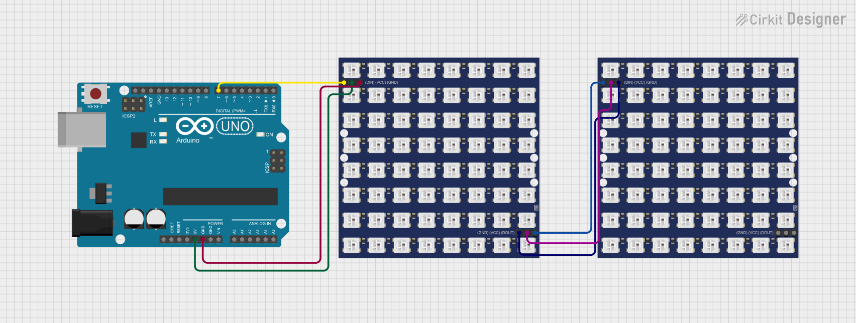
Q: How do I chain multiple matrices together?
A: Connect the DOUT pin of the first matrix to the DIN pin of the next matrix. Update the NUM_LEDS value in your code to reflect the total number of LEDs.

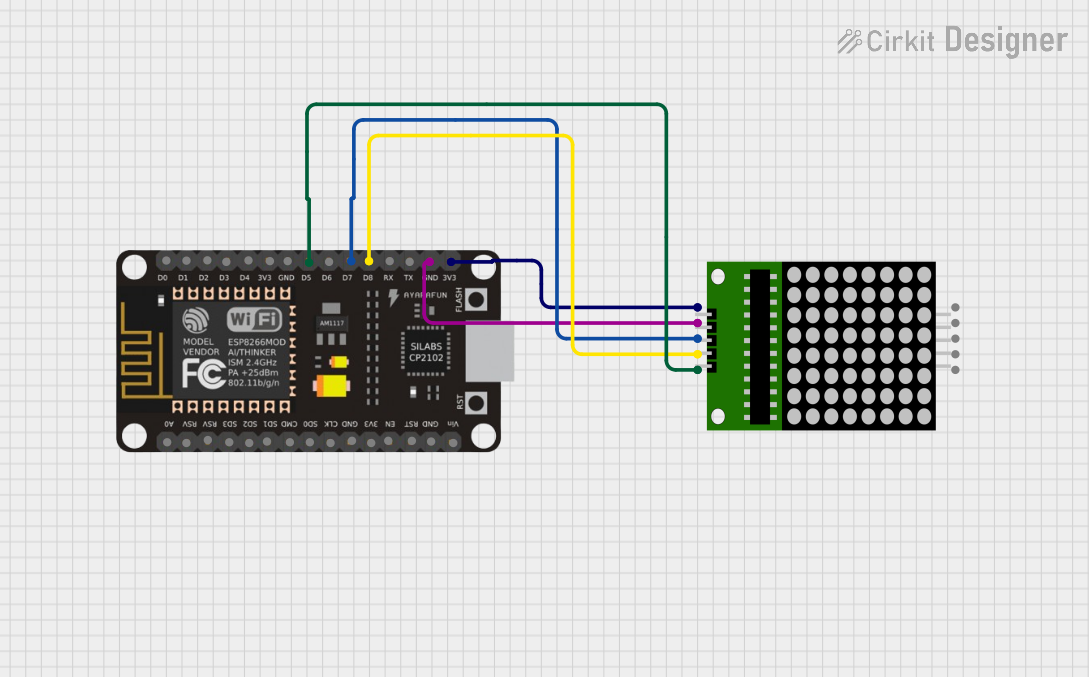
Q: Can I control the matrix with a 3.3V microcontroller?
A: Yes, the WS2812B is compatible with 3.3V logic. However, for long data lines, a level shifter may be required for reliable operation.