Cirkit Designer Logo
Cirkit Designer
Your all-in-one circuit design IDE
Home / 
Component Documentation

How to Use Arduino MEGA 2560 With WiFi Built-in - ESP8266: Examples, Pinouts, and Specs

Image of Arduino MEGA 2560 With WiFi Built-in - ESP8266
Cirkit Designer LogoDesign with Arduino MEGA 2560 With WiFi Built-in - ESP8266 in Cirkit Designer

Introduction

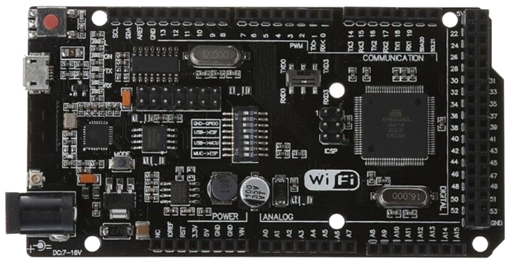
The Arduino MEGA 2560 With WiFi Built-in - ESP8266 is a versatile microcontroller board that combines the power of the ATmega2560 microcontroller with the connectivity of the ESP8266 WiFi module. This integration allows users to create advanced IoT (Internet of Things) projects with ease, enabling remote control and monitoring of devices over the internet.

This board is ideal for applications requiring a large number of I/O pins, high processing power, and wireless communication. It is particularly suited for:

  • Home automation systems
  • IoT-enabled devices
  • Robotics and industrial control systems
  • Data logging and remote monitoring

Explore Projects Built with Arduino MEGA 2560 With WiFi Built-in - ESP8266

Use Cirkit Designer to design, explore, and prototype these projects online. Some projects support real-time simulation. Click "Open Project" to start designing instantly!
Arduino Mega 2560 and ESP32 Based Environmental Monitoring and Control System
Image of Hero's Birthday: A project utilizing Arduino MEGA 2560 With WiFi Built-in - ESP8266 in a practical application
This circuit features an Arduino Mega 2560 and an ESP32 microcontroller, which are interconnected for communication. The Arduino Mega controls a DHT22 temperature and humidity sensor, a water level sensor, and a 2-channel relay that switches a water pump and two 12V fans based on temperature and water level readings. The ESP32 is set up to connect to WiFi and serve sensor data over a web server, receiving data from the Arduino via serial communication.
Cirkit Designer LogoOpen Project in Cirkit Designer
Dual ESP32-CAM and Arduino Mega 2560 Serial Communication Interface
Image of Fridge monitor: A project utilizing Arduino MEGA 2560 With WiFi Built-in - ESP8266 in a practical application
This circuit consists of two ESP32-CAM modules and an Arduino Mega 2560 microcontroller. The ESP32-CAM modules are interfaced with the Arduino Mega 2560 via serial communication, with one module connected to Serial1 (TX1/RX1) and the other to Serial2 (TX2/RX2). The Arduino Mega 2560 runs a sketch that controls an LED on pin D13, turning it on for one second and off for two seconds in a continuous loop.
Cirkit Designer LogoOpen Project in Cirkit Designer
Arduino Mega 2560 Smart Hydroponics System with Wi-Fi and Bluetooth Control
Image of JinnGarden hydroponics V1: A project utilizing Arduino MEGA 2560 With WiFi Built-in - ESP8266 in a practical application
This circuit is a smart home automation system controlled by an Arduino Mega 2560, featuring an LCD display, WiFi and Bluetooth modules, multiple sensors (temperature, humidity, and pH), and a relay module to control a water pump and LED light strips. The system is powered by a 12V power supply and allows for remote monitoring and control via WiFi and Bluetooth.
Cirkit Designer LogoOpen Project in Cirkit Designer
Arduino Mega 2560 and ESP32-CAM Sensor Integration for Environmental Monitoring
Image of Fridge monitor: A project utilizing Arduino MEGA 2560 With WiFi Built-in - ESP8266 in a practical application
This circuit features two Arduino Mega 2560 microcontrollers, an ESP32-CAM module, an Adafruit SHT31-D temperature and humidity sensor, a GY-30 BH1750FVI digital light intensity sensor, and an MPU-6050 accelerometer and gyroscope. The Arduinos are programmed to blink an LED on pin D13, with one also interfacing with the ESP32-CAM via serial communication (TX0/RX0) and the other providing power and I2C communication (SCL/SDA) to the sensors. The ESP32-CAM is connected for potential image capture or video streaming, while the sensors are set up to measure environmental conditions and motion, likely for a monitoring or control system.
Cirkit Designer LogoOpen Project in Cirkit Designer

Explore Projects Built with Arduino MEGA 2560 With WiFi Built-in - ESP8266

Use Cirkit Designer to design, explore, and prototype these projects online. Some projects support real-time simulation. Click "Open Project" to start designing instantly!
Image of Hero's Birthday: A project utilizing Arduino MEGA 2560 With WiFi Built-in - ESP8266 in a practical application
Arduino Mega 2560 and ESP32 Based Environmental Monitoring and Control System
This circuit features an Arduino Mega 2560 and an ESP32 microcontroller, which are interconnected for communication. The Arduino Mega controls a DHT22 temperature and humidity sensor, a water level sensor, and a 2-channel relay that switches a water pump and two 12V fans based on temperature and water level readings. The ESP32 is set up to connect to WiFi and serve sensor data over a web server, receiving data from the Arduino via serial communication.
Cirkit Designer LogoOpen Project in Cirkit Designer
Image of Fridge monitor: A project utilizing Arduino MEGA 2560 With WiFi Built-in - ESP8266 in a practical application
Dual ESP32-CAM and Arduino Mega 2560 Serial Communication Interface
This circuit consists of two ESP32-CAM modules and an Arduino Mega 2560 microcontroller. The ESP32-CAM modules are interfaced with the Arduino Mega 2560 via serial communication, with one module connected to Serial1 (TX1/RX1) and the other to Serial2 (TX2/RX2). The Arduino Mega 2560 runs a sketch that controls an LED on pin D13, turning it on for one second and off for two seconds in a continuous loop.
Cirkit Designer LogoOpen Project in Cirkit Designer
Image of JinnGarden hydroponics V1: A project utilizing Arduino MEGA 2560 With WiFi Built-in - ESP8266 in a practical application
Arduino Mega 2560 Smart Hydroponics System with Wi-Fi and Bluetooth Control
This circuit is a smart home automation system controlled by an Arduino Mega 2560, featuring an LCD display, WiFi and Bluetooth modules, multiple sensors (temperature, humidity, and pH), and a relay module to control a water pump and LED light strips. The system is powered by a 12V power supply and allows for remote monitoring and control via WiFi and Bluetooth.
Cirkit Designer LogoOpen Project in Cirkit Designer
Image of Fridge monitor: A project utilizing Arduino MEGA 2560 With WiFi Built-in - ESP8266 in a practical application
Arduino Mega 2560 and ESP32-CAM Sensor Integration for Environmental Monitoring
This circuit features two Arduino Mega 2560 microcontrollers, an ESP32-CAM module, an Adafruit SHT31-D temperature and humidity sensor, a GY-30 BH1750FVI digital light intensity sensor, and an MPU-6050 accelerometer and gyroscope. The Arduinos are programmed to blink an LED on pin D13, with one also interfacing with the ESP32-CAM via serial communication (TX0/RX0) and the other providing power and I2C communication (SCL/SDA) to the sensors. The ESP32-CAM is connected for potential image capture or video streaming, while the sensors are set up to measure environmental conditions and motion, likely for a monitoring or control system.
Cirkit Designer LogoOpen Project in Cirkit Designer

Technical Specifications

Key Technical Details

Specification Value
Microcontroller ATmega2560
Operating Voltage 5V
Input Voltage (recommended) 7-12V
Input Voltage (limit) 6-20V
Digital I/O Pins 54 (15 PWM outputs)
Analog Input Pins 16
Flash Memory (ATmega2560) 256 KB (8 KB used by bootloader)
SRAM 8 KB
EEPROM 4 KB
Clock Speed 16 MHz
WiFi Module ESP8266
Communication Interfaces UART, SPI, I2C, WiFi

Pin Configuration and Descriptions

ATmega2560 Pinout

Pin Number Pin Name Description
0-53 Digital I/O General-purpose digital input/output pins
0-15 PWM Pins Digital pins with PWM output capability
A0-A15 Analog Inputs Analog input pins (10-bit resolution)
20-21 I2C (SDA, SCL) I2C communication pins
0-3, 14-19 UART (TX, RX) Serial communication pins
50-53 SPI (MISO, MOSI, SCK, SS) SPI communication pins
GND Ground Ground connection
5V, 3.3V Power Output Regulated power output pins

ESP8266 WiFi Module Pinout

Pin Name Description
TX Transmit data (UART communication)
RX Receive data (UART communication)
EN Enable pin (active high)
GPIO0, GPIO2 General-purpose I/O pins
GND Ground connection
VCC Power input (3.3V)

Usage Instructions

How to Use the Component in a Circuit

  1. Powering the Board:

    • Supply the board with 7-12V via the DC barrel jack or VIN pin. Alternatively, use the USB connection for power and programming.
    • Ensure the ESP8266 module is powered with 3.3V (internally regulated by the board).
  2. Programming the ATmega2560:

    • Connect the board to your computer via USB.
    • Open the Arduino IDE, select Arduino Mega 2560 as the board, and choose the correct COM port.
    • Write and upload your sketch to the ATmega2560.
  3. Programming the ESP8266:

    • Switch the board to "ESP8266 mode" using the onboard DIP switches (refer to the board's manual for the correct configuration).
    • Use the Arduino IDE or a dedicated ESP8266 flashing tool to upload firmware or sketches to the ESP8266.
  4. Establishing WiFi Connectivity:

    • Use the ESP8266 to connect to a WiFi network. The ATmega2560 can communicate with the ESP8266 via UART to send/receive data over the internet.

Important Considerations and Best Practices

  • Voltage Levels: The ESP8266 operates at 3.3V. Avoid applying 5V directly to its pins to prevent damage.
  • DIP Switch Configuration: Ensure the DIP switches are set correctly for programming or communication modes.
  • Serial Communication: Use Serial1, Serial2, or Serial3 for communication with the ESP8266 to avoid conflicts with the USB serial interface (Serial).

Example Code: Connecting to WiFi and Sending Data

The following example demonstrates how to connect the ESP8266 to a WiFi network and send data to a server.

#include <SoftwareSerial.h>

// Define RX and TX pins for ESP8266 communication
SoftwareSerial espSerial(18, 19); // RX = pin 18, TX = pin 19

void setup() {
  // Initialize serial communication
  Serial.begin(9600); // For debugging
  espSerial.begin(115200); // ESP8266 baud rate

  // Connect to WiFi
  sendCommand("AT+RST", 2000); // Reset the ESP8266
  sendCommand("AT+CWMODE=1", 1000); // Set WiFi mode to Station
  sendCommand("AT+CWJAP=\"YourSSID\",\"YourPassword\"", 5000); // Connect to WiFi

  // Start TCP connection
  sendCommand("AT+CIPSTART=\"TCP\",\"example.com\",80", 5000);
  
  // Send HTTP GET request
  sendCommand("AT+CIPSEND=18", 2000); // Specify data length
  espSerial.println("GET / HTTP/1.1\r\n\r\n");
}

void loop() {
  // Continuously check for ESP8266 responses
  while (espSerial.available()) {
    Serial.write(espSerial.read());
  }
}

// Function to send AT commands to ESP8266
void sendCommand(String command, int delayTime) {
  espSerial.println(command);
  delay(delayTime);
  while (espSerial.available()) {
    Serial.write(espSerial.read());
  }
}

Note: Replace "YourSSID" and "YourPassword" with your WiFi credentials. Ensure the ESP8266 baud rate matches the one set in the code.

Troubleshooting and FAQs

Common Issues and Solutions

  1. ESP8266 Not Responding:

    • Ensure the DIP switches are configured correctly for ESP8266 communication.
    • Verify the ESP8266 is powered with 3.3V and not 5V.
  2. WiFi Connection Fails:

    • Double-check the SSID and password in your code.
    • Ensure the WiFi network is within range and operational.
  3. Serial Communication Conflicts:

    • Avoid using Serial for both debugging and ESP8266 communication. Use Serial1, Serial2, or Serial3 instead.
  4. Code Upload Fails:

    • Ensure the correct board and COM port are selected in the Arduino IDE.
    • Disconnect any external devices connected to the RX/TX pins during programming.

FAQs

Q: Can I use the ESP8266 and ATmega2560 simultaneously?
A: Yes, the ATmega2560 can communicate with the ESP8266 via UART while running its own program. Ensure proper DIP switch settings.

Q: How do I update the ESP8266 firmware?
A: Switch the board to "ESP8266 mode" using the DIP switches, then use a flashing tool to upload the firmware.

Q: What is the maximum WiFi range?
A: The ESP8266 typically has a range of 30-50 meters indoors and up to 100 meters outdoors, depending on environmental factors.

By following this documentation, you can effectively utilize the Arduino MEGA 2560 With WiFi Built-in - ESP8266 for your IoT and automation projects.