
How to Use SOIC-14: Examples, Pinouts, and Specs
 Design with SOIC-14 in Cirkit Designer
Introduction
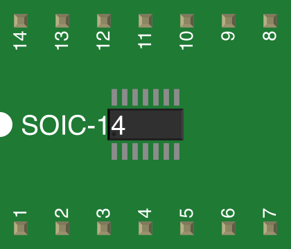
The SOIC-14 (Small Outline Integrated Circuit with 14 pins) is a surface-mount package designed for integrated circuits. It features a compact footprint, making it ideal for applications where space is limited. The SOIC-14 package is widely used in consumer electronics, automotive systems, industrial equipment, and communication devices. Its design provides a balance between miniaturization and ease of handling during assembly.
Explore Projects Built with SOIC-14
 Open Project in Cirkit Designer
 Open Project in Cirkit Designer
 Open Project in Cirkit Designer
 Open Project in Cirkit Designer
Explore Projects Built with SOIC-14
Open Project in Cirkit DesignerOpen Project in Cirkit DesignerOpen Project in Cirkit DesignerOpen Project in Cirkit DesignerCommon Applications:
- Microcontrollers and digital ICs
- Analog ICs such as operational amplifiers
- Communication modules
- Power management circuits
- Sensor interface circuits
Technical Specifications
Key Technical Details:
- Package Type: SOIC (Small Outline Integrated Circuit)
- Number of Pins: 14
- Pin Pitch: 1.27 mm (distance between adjacent pins)
- Body Width: 3.9 mm (narrow SOIC) or 7.5 mm (wide SOIC)
- Body Length: 8.65 mm
- Height: 1.75 mm (maximum)
- Mounting Type: Surface Mount Technology (SMT)
- Thermal Resistance: Varies by IC, typically 50–100 °C/W
- Operating Temperature Range: -40 °C to +125 °C (dependent on the IC inside)
- Moisture Sensitivity Level (MSL): Typically Level 1 or 2
Pin Configuration and Descriptions:
The pin configuration of the SOIC-14 depends on the specific IC housed within the package. Below is a generic example for a typical SOIC-14 operational amplifier (quad op-amp):
| Pin Number | Pin Name | Description |
|---|---|---|
| 1 | OUT A | Output of Op-Amp A |
| 2 | IN- A | Inverting Input of Op-Amp A |
| 3 | IN+ A | Non-Inverting Input of Op-Amp A |
| 4 | VCC- (GND) | Negative Power Supply or Ground |
| 5 | IN+ B | Non-Inverting Input of Op-Amp B |
| 6 | IN- B | Inverting Input of Op-Amp B |
| 7 | OUT B | Output of Op-Amp B |
| 8 | OUT C | Output of Op-Amp C |
| 9 | IN- C | Inverting Input of Op-Amp C |
| 10 | IN+ C | Non-Inverting Input of Op-Amp C |
| 11 | VCC+ | Positive Power Supply |
| 12 | IN+ D | Non-Inverting Input of Op-Amp D |
| 13 | IN- D | Inverting Input of Op-Amp D |
| 14 | OUT D | Output of Op-Amp D |
Note: Always refer to the datasheet of the specific IC for accurate pin descriptions.
Usage Instructions
How to Use the SOIC-14 in a Circuit:
- Soldering:
- Use a soldering iron or reflow soldering process to mount the SOIC-14 onto a PCB.
- Ensure proper alignment of pins with the PCB pads to avoid solder bridges.
- Power Supply:
- Connect the VCC+ and VCC- (or GND) pins to the appropriate power supply levels as specified in the IC datasheet.
- Signal Connections:
- Connect the input and output pins according to the circuit design.
- Use decoupling capacitors near the power supply pins to reduce noise.
- Thermal Management:
- Ensure adequate heat dissipation, especially for ICs with high power consumption.
Best Practices:
- Use a flux pen to improve soldering quality and reduce oxidation.
- Verify the orientation of the IC before soldering (look for the dot or notch indicating Pin 1).
- Avoid excessive heat during soldering to prevent damage to the IC.
- Use a multimeter to check for short circuits after soldering.
Example: Connecting a SOIC-14 IC to an Arduino UNO
Below is an example of interfacing a SOIC-14 operational amplifier with an Arduino UNO to amplify an analog signal:
// Example: Reading an amplified signal from a SOIC-14 Op-Amp
// Connect the output of the Op-Amp to Arduino's analog pin A0

const int analogPin = A0; // Define the analog input pin
int sensorValue = 0;      // Variable to store the analog reading

void setup() {
  Serial.begin(9600); // Initialize serial communication at 9600 baud
}

void loop() {
  sensorValue = analogRead(analogPin); // Read the analog value
  Serial.print("Sensor Value: ");      // Print the value to the Serial Monitor
  Serial.println(sensorValue);
  delay(500); // Wait for 500ms before the next reading
}
Note: Ensure the Op-Amp is powered correctly and the input signal is within the operating range of the IC.
Troubleshooting and FAQs
Common Issues:
Solder Bridges:
- Problem: Adjacent pins are shorted due to excess solder.
- Solution: Use a solder wick or desoldering pump to remove excess solder.
Incorrect Orientation:
- Problem: The IC is soldered in the wrong orientation.
- Solution: Check for the Pin 1 indicator (dot or notch) before soldering.
No Output Signal:
- Problem: The IC is not powered or connections are incorrect.
- Solution: Verify power supply connections and ensure all pins are connected as per the circuit design.
Overheating:
- Problem: The IC becomes excessively hot during operation.
- Solution: Check for overvoltage or excessive current draw. Add a heatsink or improve PCB thermal design if necessary.
FAQs:
Q: Can I use a SOIC-14 IC on a breadboard?
- A: Not directly. You will need a SOIC-to-DIP adapter to use it with a breadboard.
Q: How do I clean the PCB after soldering a SOIC-14?
- A: Use isopropyl alcohol and a soft brush to remove flux residues.
Q: What is the difference between narrow and wide SOIC-14 packages?
- A: The difference lies in the body width. Narrow SOIC-14 has a width of 3.9 mm, while wide SOIC-14 has a width of 7.5 mm. Ensure your PCB footprint matches the package type.
Q: Can I hand-solder a SOIC-14 IC?
- A: Yes, but it requires precision. Use a fine-tipped soldering iron and flux for best results.
By following this documentation, you can effectively integrate and troubleshoot SOIC-14 components in your projects. Always refer to the specific IC datasheet for detailed information.