How to Use Keypad 2x2: Examples, Pinouts, and Specs
Introduction
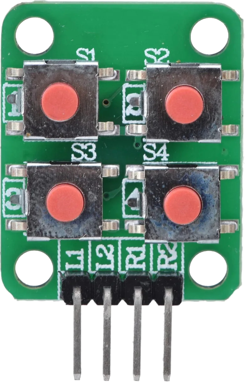
The Keypad 2x2 is a compact input device featuring a grid of 2 rows and 2 columns of buttons. It allows users to input data or commands through tactile interaction. This simple yet versatile component is widely used in projects requiring user input, such as password entry systems, menu navigation, or basic control interfaces.
Explore Projects Built with Keypad 2x2

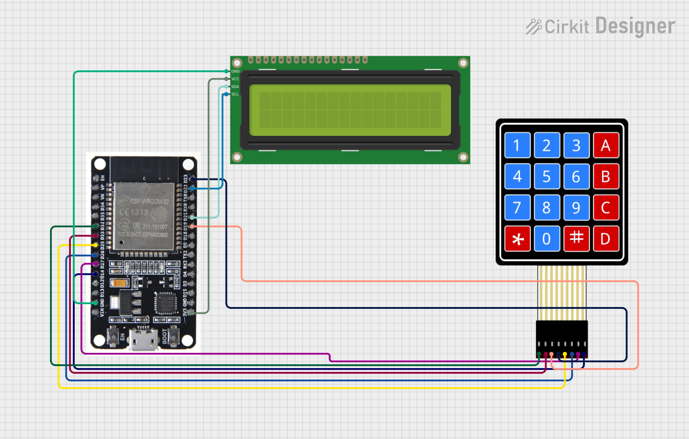
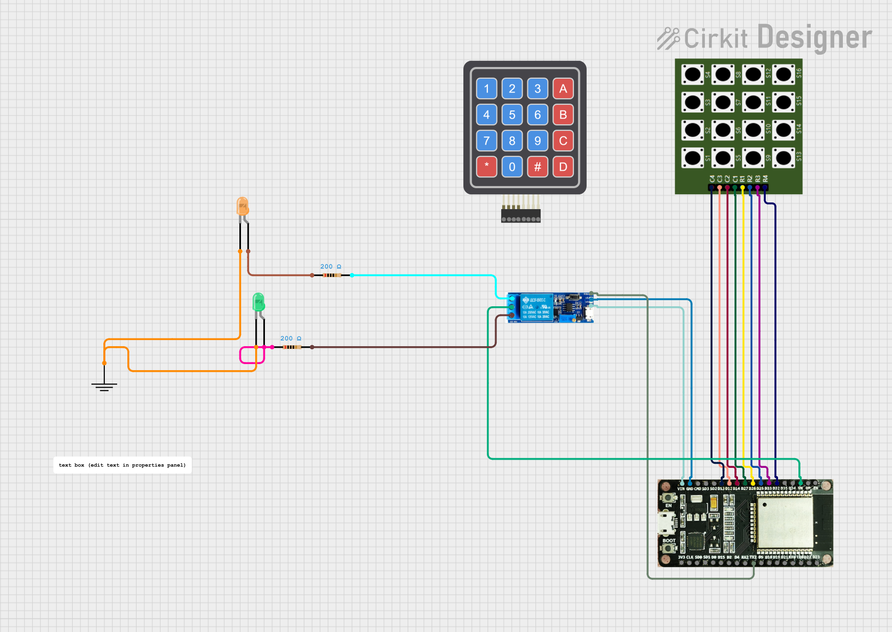
Explore Projects Built with Keypad 2x2
Common Applications and Use Cases
- Security systems (e.g., PIN entry for locks)
- Menu-driven interfaces for embedded systems
- Simple control panels for DIY electronics
- Educational projects for learning about matrix keypads
Technical Specifications
The Keypad 2x2 operates as a matrix keypad, where each button press connects a specific row and column. This design minimizes the number of pins required for operation.
Key Specifications
- Number of Buttons: 4 (2 rows × 2 columns)
- Operating Voltage: 3.3V to 5V
- Current Consumption: < 10mA
- Button Type: Momentary tactile switches
- Dimensions: Varies by manufacturer, typically compact
- Interface: 4-pin matrix (2 row pins, 2 column pins)
Pin Configuration and Descriptions
The Keypad 2x2 has four pins, which correspond to the rows and columns of the matrix. Below is the pinout:
| Pin | Label | Description |
|---|---|---|
| 1 | R1 | Row 1 connection |
| 2 | R2 | Row 2 connection |
| 3 | C1 | Column 1 connection |
| 4 | C2 | Column 2 connection |
Usage Instructions
How to Use the Keypad 2x2 in a Circuit
- Connect the Pins:
- Connect the row pins (R1, R2) and column pins (C1, C2) to the microcontroller's GPIO pins.
- Use pull-up or pull-down resistors if necessary to stabilize the signal.
- Scan the Keypad:
- To detect a button press, set one row pin HIGH and the others LOW, then check the column pins for a HIGH signal.
- Repeat this process for each row to identify the pressed button.
- Debounce the Input:
- Implement software or hardware debouncing to avoid false triggers caused by mechanical switch bounce.
Important Considerations and Best Practices
- Voltage Compatibility: Ensure the keypad's operating voltage matches your microcontroller's logic level (e.g., 3.3V or 5V).
- Debouncing: Use a software debounce routine or a capacitor to filter out noise from button presses.
- Pin Mapping: Clearly document the GPIO pins used for rows and columns in your project for easier debugging.
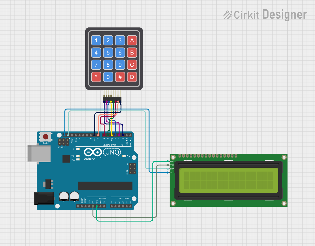
Example Code for Arduino UNO
Below is an example of how to use the Keypad 2x2 with an Arduino UNO. This code detects button presses and prints the corresponding button to the Serial Monitor.
#include <Keypad.h>

// Define the rows and columns of the keypad
const byte ROWS = 2; // Number of rows
const byte COLS = 2; // Number of columns

// Define the keymap for the 2x2 keypad
char keys[ROWS][COLS] = {
  {'1', '2'},
  {'3', '4'}
};

// Define the row and column pins connected to the Arduino
byte rowPins[ROWS] = {9, 8}; // Connect to R1, R2
byte colPins[COLS] = {7, 6}; // Connect to C1, C2

// Create the Keypad object
Keypad keypad = Keypad(makeKeymap(keys), rowPins, colPins, ROWS, COLS);

void setup() {
  Serial.begin(9600); // Initialize serial communication
  Serial.println("Keypad 2x2 Test");
}

void loop() {
  char key = keypad.getKey(); // Check for key press

  if (key) { // If a key is pressed
    Serial.print("Key Pressed: ");
    Serial.println(key); // Print the key to the Serial Monitor
  }
}
Notes:
- Install the Keypad library in the Arduino IDE before using this code.
- Adjust the
rowPinsandcolPinsarrays to match your wiring.
Troubleshooting and FAQs
Common Issues and Solutions
No Key Press Detected:
- Verify the wiring between the keypad and the microcontroller.
- Check that the row and column pins are correctly assigned in the code.
- Ensure the keypad is powered within its operating voltage range.
Multiple Keys Detected at Once:
- Check for short circuits between row and column pins.
- Implement proper debouncing in the code to avoid false triggers.
Incorrect Key Mapping:
- Double-check the
keysarray in the code to ensure it matches the physical layout of the keypad. - Verify the row and column pin connections.
- Double-check the
FAQs
Q: Can I use the Keypad 2x2 with a 3.3V microcontroller?
A: Yes, the Keypad 2x2 is compatible with both 3.3V and 5V logic levels. Ensure your microcontroller's GPIO pins can detect the voltage levels.
Q: How do I expand this to a larger keypad?
A: The same principles apply to larger keypads. Update the keys array, rowPins, and colPins arrays to match the new keypad's layout.
Q: Do I need external pull-up resistors?
A: Most microcontrollers have internal pull-up resistors that can be enabled in the code. If not, you can use external resistors (e.g., 10kΩ) to stabilize the signal.
By following this documentation, you can effectively integrate the Keypad 2x2 into your projects and troubleshoot common issues with ease.