How to Use keypad 3x4: Examples, Pinouts, and Specs
Introduction
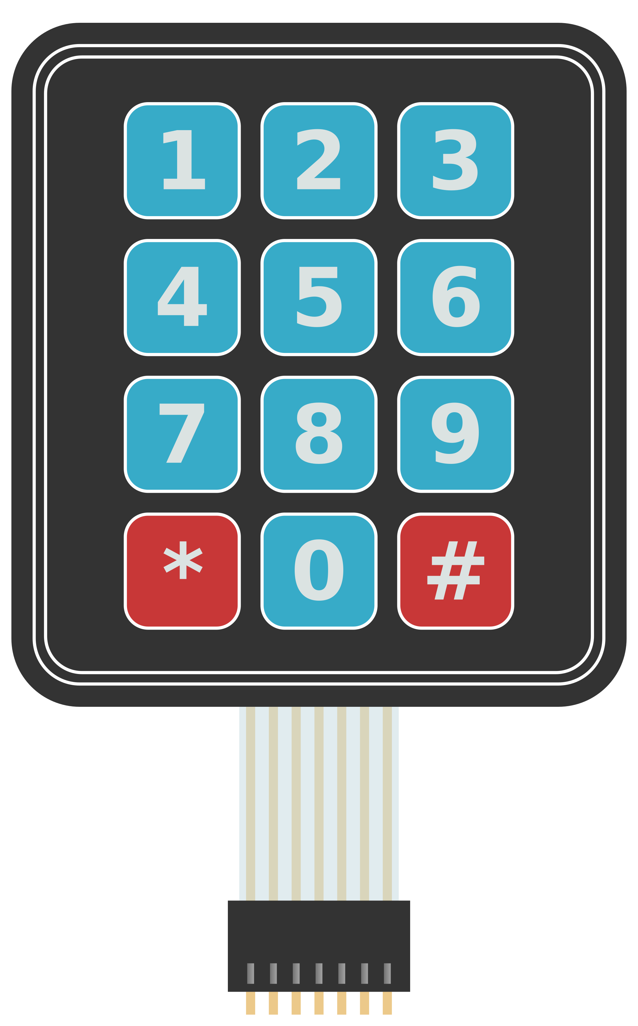
- A 3x4 keypad is an input device consisting of 12 buttons arranged in a grid of 3 rows and 4 columns. Each button represents a unique combination of a row and a column.
- This component is commonly used in electronic devices such as calculators, security systems, door locks, and embedded systems where user input is required.
Explore Projects Built with keypad 3x4


Explore Projects Built with keypad 3x4
Technical Specifications
- Number of Buttons: 12 (3 rows × 4 columns)
- Operating Voltage: 3.3V to 5V
- Current Consumption: Typically less than 10mA
- Button Type: Momentary push buttons
- Interface: Matrix (row-column scanning)
- Dimensions: Varies by manufacturer, typically around 70mm × 50mm
- Connector Type: 7-pin interface (3 row pins + 4 column pins)
Pin Configuration and Descriptions
| Pin Number | Label | Description |
|---|---|---|
| 1 | R1 | Row 1 connection |
| 2 | R2 | Row 2 connection |
| 3 | R3 | Row 3 connection |
| 4 | C1 | Column 1 connection |
| 5 | C2 | Column 2 connection |
| 6 | C3 | Column 3 connection |
| 7 | C4 | Column 4 connection |
Usage Instructions
How to Use the Keypad in a Circuit
Wiring the Keypad:
- Connect the 7 pins of the keypad to a microcontroller or microprocessor.
- The row pins (R1, R2, R3) and column pins (C1, C2, C3, C4) should be connected to GPIO pins of the microcontroller.
- Use pull-up or pull-down resistors if required by your circuit design.
Scanning the Keypad:
- The microcontroller sends signals to the column pins and reads the row pins to detect which button is pressed.
- When a button is pressed, it creates a connection between a specific row and column.
Debouncing:
- Implement software or hardware debouncing to avoid false readings caused by mechanical bouncing of the buttons.
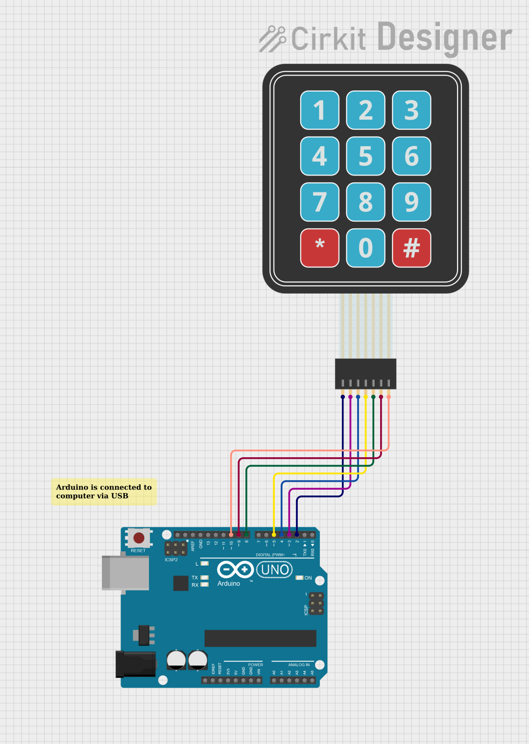
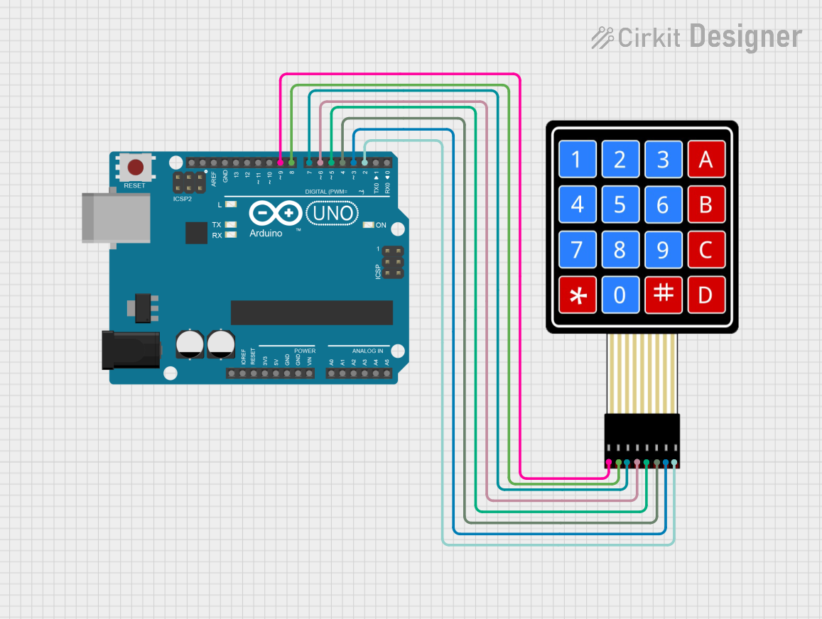
Example: Using the Keypad with Arduino UNO
Below is an example of how to use a 3x4 keypad with an Arduino UNO. This example uses the Keypad library, which simplifies interfacing with the keypad.
Circuit Connections
- Connect the keypad pins to the Arduino as follows:
- R1 → Pin 9
- R2 → Pin 8
- R3 → Pin 7
- C1 → Pin 6
- C2 → Pin 5
- C3 → Pin 4
- C4 → Pin 3
Code Example
#include <Keypad.h>

// Define the rows and columns of the keypad
const byte ROWS = 3; // 3 rows
const byte COLS = 4; // 4 columns

// Define the keymap for the keypad
char keys[ROWS][COLS] = {
  {'1', '2', '3', 'A'},
  {'4', '5', '6', 'B'},
  {'7', '8', '9', 'C'}
};

// Define the row and column pins connected to the Arduino
byte rowPins[ROWS] = {9, 8, 7};    // Connect to R1, R2, R3
byte colPins[COLS] = {6, 5, 4, 3}; // Connect to C1, C2, C3, C4

// Create a Keypad object
Keypad keypad = Keypad(makeKeymap(keys), rowPins, colPins, ROWS, COLS);

void setup() {
  Serial.begin(9600); // Initialize serial communication
  Serial.println("Keypad Test: Press a key");
}

void loop() {
  char key = keypad.getKey(); // Get the key pressed

  if (key) {
    // If a key is pressed, print it to the Serial Monitor
    Serial.print("Key Pressed: ");
    Serial.println(key);
  }
}
Important Considerations and Best Practices
- Ensure the keypad is securely connected to avoid loose connections that may cause unreliable readings.
- Use a stable power supply to prevent voltage fluctuations that could affect the keypad's performance.
- If the keypad is exposed to the environment, consider using a protective cover to prevent dust or moisture from interfering with the buttons.
Troubleshooting and FAQs
Common Issues and Solutions
No Key Press Detected:
- Check the wiring between the keypad and the microcontroller.
- Verify that the correct pins are defined in the code.
Incorrect Key Press Detected:
- Ensure the keymap in the code matches the physical layout of the keypad.
- Check for short circuits between row and column pins.
Multiple Keys Detected Simultaneously:
- Implement proper debouncing in the code to filter out false signals.
- Inspect the keypad for stuck or damaged buttons.
Keypad Not Responding:
- Confirm that the microcontroller's GPIO pins are configured correctly (input/output mode).
- Test the keypad with a multimeter to ensure all buttons are functioning.
FAQs
Q: Can I use the 3x4 keypad with a 3.3V microcontroller?
A: Yes, the keypad is compatible with both 3.3V and 5V systems. Ensure the microcontroller's GPIO pins can detect the voltage levels.
Q: How do I extend the keypad's cable length?
A: Use shielded cables to reduce noise and interference. Keep the cable length as short as possible for reliable operation.
Q: Can I use the keypad for multiple simultaneous key presses?
A: The 3x4 keypad is not designed for multi-key detection. It is best suited for single key presses at a time.
Q: Is the keypad waterproof?
A: Most 3x4 keypads are not waterproof. If needed, use a waterproof enclosure or a specialized waterproof keypad.