How to Use Headphone Jack Female: Examples, Pinouts, and Specs
Introduction
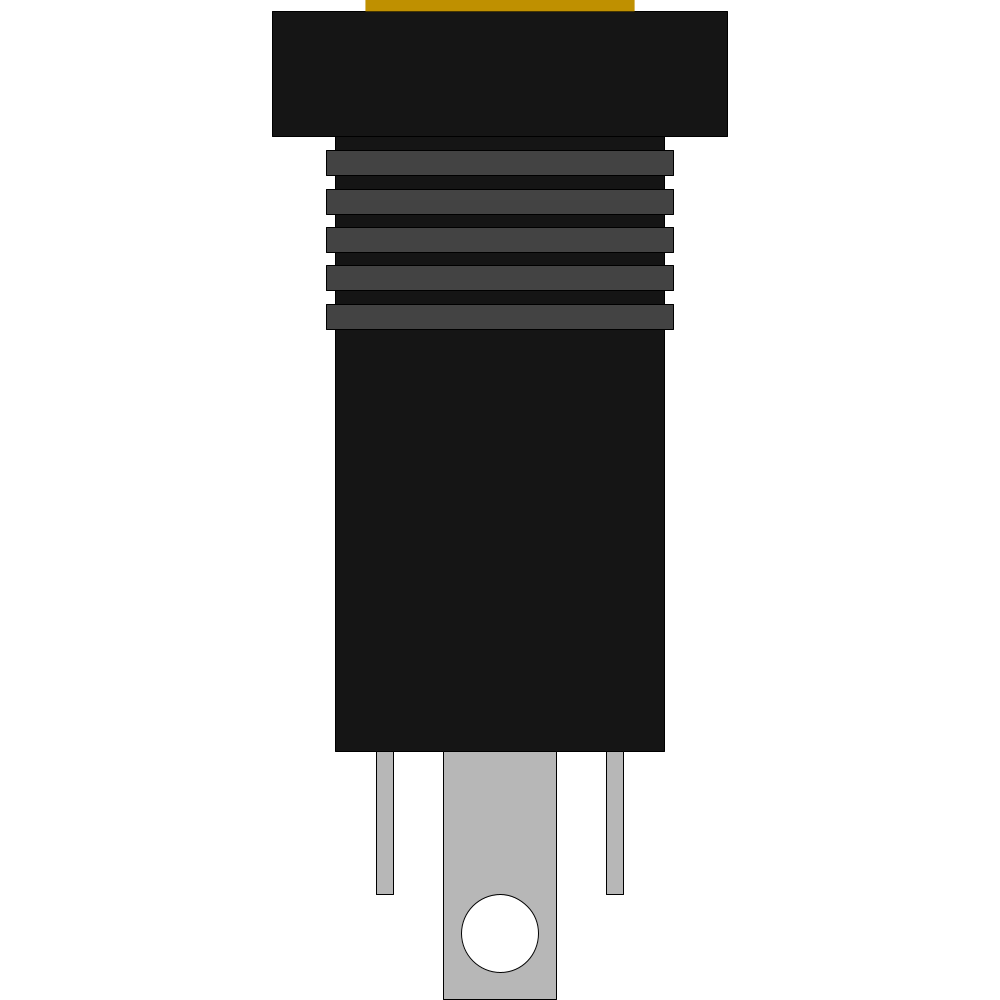
The Headphone Jack Female is a standard audio connector designed to receive a male headphone plug, enabling audio output from various devices. It is commonly used in smartphones, computers, audio equipment, and DIY electronics projects. This component facilitates the transmission of stereo or mono audio signals and is available in different sizes, such as 3.5mm (most common), 2.5mm, and 6.35mm.
Explore Projects Built with Headphone Jack Female
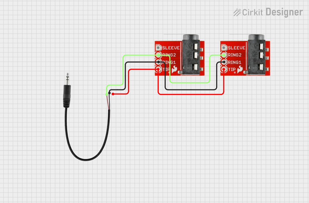

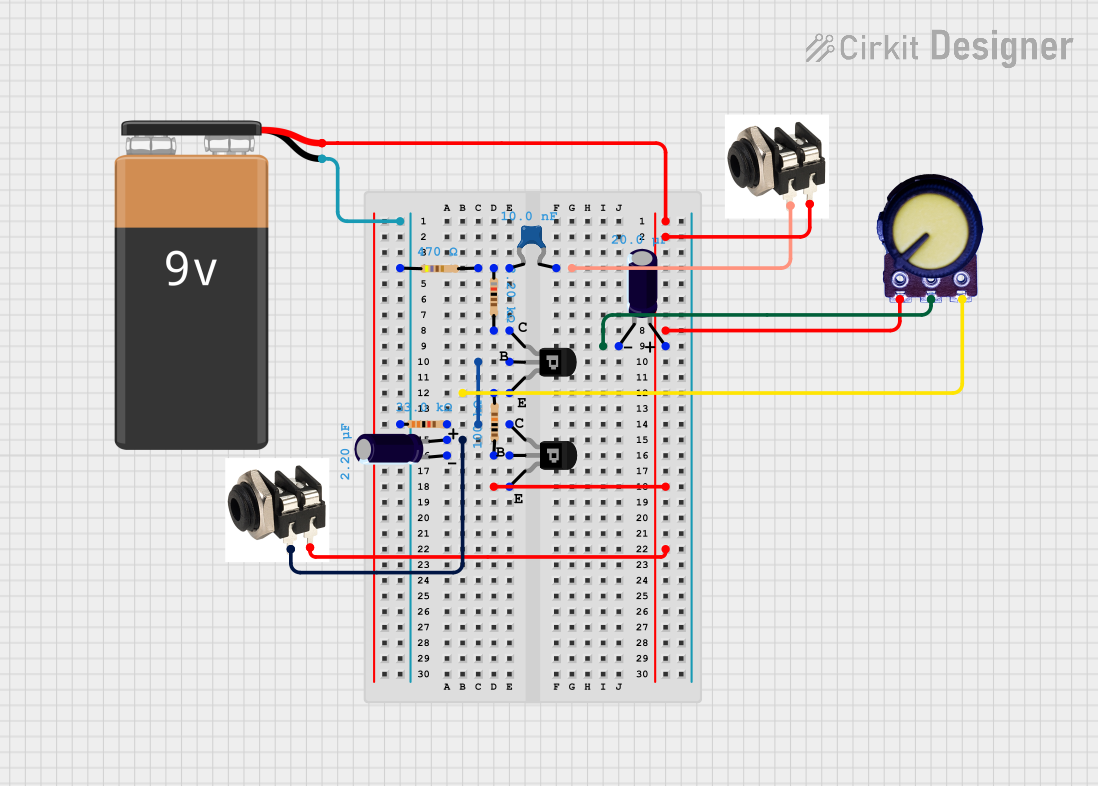
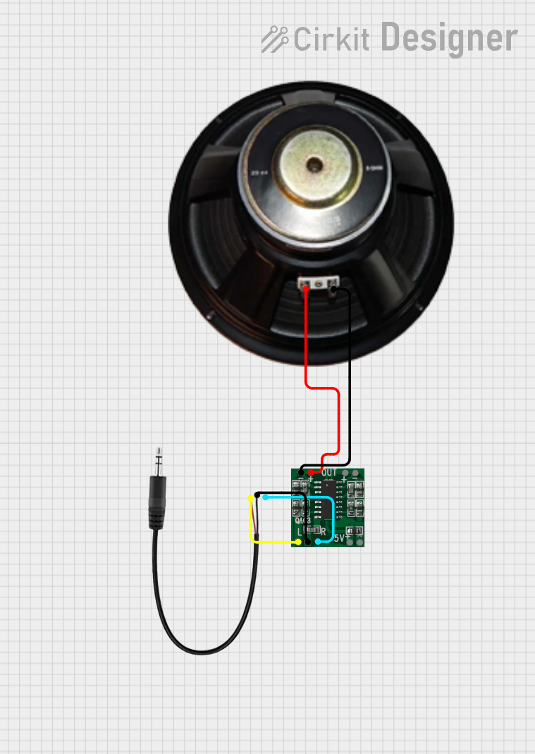
Explore Projects Built with Headphone Jack Female
Common Applications and Use Cases
- Audio output for headphones, speakers, and amplifiers
- DIY audio projects and prototyping
- Integration into custom audio devices
- Repair or replacement of damaged headphone jacks in electronics
Technical Specifications
Below are the general technical specifications for a standard 3.5mm stereo headphone jack female:
| Parameter | Value |
|---|---|
| Connector Type | 3.5mm TRS (Tip-Ring-Sleeve) |
| Number of Contacts | 3 (Stereo: Left, Right, Ground) |
| Mounting Type | Through-hole or surface-mount |
| Voltage Rating | 12V DC (typical) |
| Current Rating | 1A (maximum) |
| Material | Plastic housing, metal contacts |
| Contact Resistance | ≤ 50 mΩ |
| Insulation Resistance | ≥ 100 MΩ |
| Operating Temperature | -25°C to +85°C |
Pin Configuration and Descriptions
The 3.5mm stereo headphone jack female typically has three pins corresponding to the Tip, Ring, and Sleeve of the male plug. Below is the pin configuration:
| Pin Name | Description |
|---|---|
| Tip (T) | Left audio channel |
| Ring (R) | Right audio channel |
| Sleeve (S) | Ground (common return path for audio) |
For mono headphone jacks, there are only two pins: Tip (audio signal) and Sleeve (ground).
Usage Instructions
How to Use the Component in a Circuit
- Identify the Pins: Locate the Tip, Ring, and Sleeve pins on the headphone jack. Refer to the pin configuration table above.
- Connect to Audio Source:
- Connect the Tip pin to the left audio channel output of your audio source.
- Connect the Ring pin to the right audio channel output.
- Connect the Sleeve pin to the ground of your circuit.
- Mounting: Secure the headphone jack to your PCB or enclosure using the through-hole or surface-mount pads.
- Test the Connection: Insert a compatible male headphone plug into the jack and verify audio output.
Important Considerations and Best Practices
- Signal Integrity: Use shielded cables to minimize noise and interference in audio signals.
- Voltage and Current Ratings: Ensure the audio source does not exceed the voltage and current ratings of the headphone jack.
- Mechanical Stress: Avoid excessive force when inserting or removing the headphone plug to prevent damage to the jack.
- Soldering: Use proper soldering techniques to ensure reliable electrical connections without short circuits.
Example: Connecting to an Arduino UNO
The headphone jack can be used with an Arduino UNO to output audio signals via a digital-to-analog converter (DAC) or PWM. Below is an example of generating a simple tone:
// Example: Generating a tone using Arduino and a headphone jack
// Connect the Tip pin to Arduino pin 9 (PWM output)
// Connect the Sleeve pin to GND

void setup() {
  // No setup required for tone generation
}

void loop() {
  // Generate a 1kHz tone on pin 9
  tone(9, 1000); // Pin 9, frequency 1000 Hz
  delay(1000);   // Play tone for 1 second
  noTone(9);     // Stop tone
  delay(1000);   // Wait for 1 second
}
Note: Use a resistor (e.g., 100Ω) in series with the Tip pin to limit current and protect the Arduino.
Troubleshooting and FAQs
Common Issues Users Might Face
No Audio Output:
- Cause: Incorrect pin connections or loose solder joints.
- Solution: Verify the connections and ensure proper soldering.
Distorted Audio:
- Cause: Signal interference or exceeding voltage/current ratings.
- Solution: Use shielded cables and ensure the audio source is within the jack's specifications.
Loose Connection:
- Cause: Worn-out or damaged jack.
- Solution: Replace the headphone jack with a new one.
Short Circuit:
- Cause: Solder bridges between pins.
- Solution: Inspect and re-solder the connections carefully.
FAQs
Q1: Can I use a 3.5mm headphone jack for mono audio?
A1: Yes, you can use a stereo jack for mono audio by connecting the Tip and Ring pins together to the audio signal and the Sleeve pin to ground.
Q2: What is the difference between TRS and TRRS jacks?
A2: TRS (Tip-Ring-Sleeve) jacks support stereo audio, while TRRS (Tip-Ring-Ring-Sleeve) jacks add an extra ring for microphone input or additional functionality.
Q3: Can I use this jack for high-power audio signals?
A3: No, the headphone jack is designed for low-power audio signals. For high-power applications, use appropriate connectors and amplifiers.
Q4: How do I clean a dirty headphone jack?
A4: Use a cotton swab lightly dampened with isopropyl alcohol to clean the contacts. Avoid using excessive liquid.