
How to Use CT PZEM-004T 100A: Examples, Pinouts, and Specs
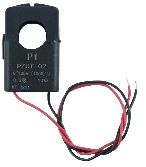
 Design with CT PZEM-004T 100A in Cirkit Designer
Introduction
The CT PZEM-004T 100A is a multifunctional energy meter designed for AC circuits. It is capable of measuring key electrical parameters such as voltage, current, power, energy, and frequency. With a current handling capacity of up to 100A, this device is ideal for monitoring and managing electrical consumption in residential, commercial, and industrial applications. Its compact design and ease of integration make it a popular choice for energy monitoring systems.
Explore Projects Built with CT PZEM-004T 100A
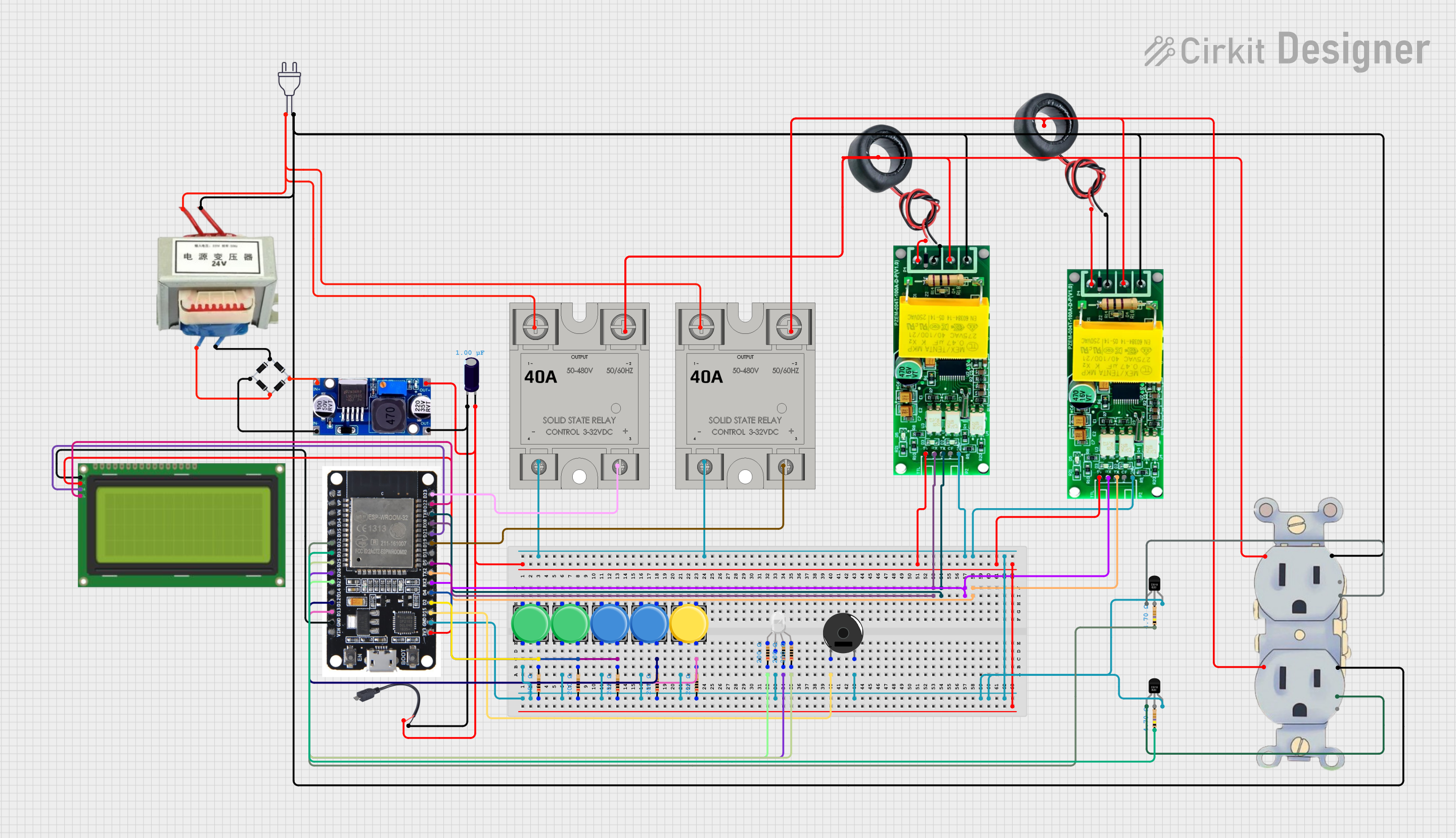 Open Project in Cirkit Designer
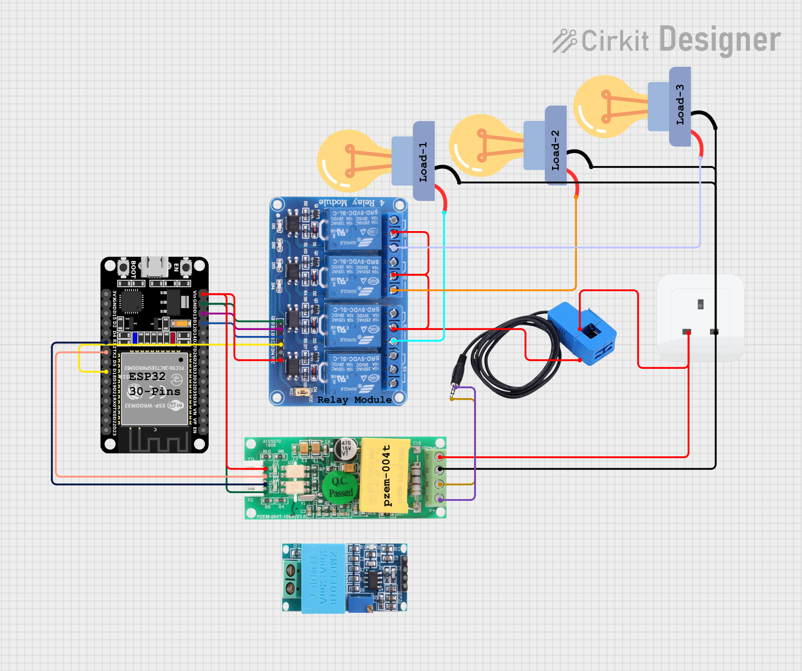 Open Project in Cirkit Designer
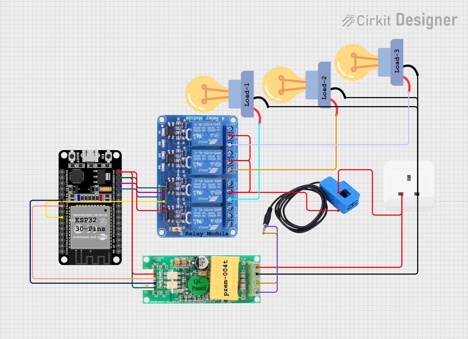 Open Project in Cirkit Designer
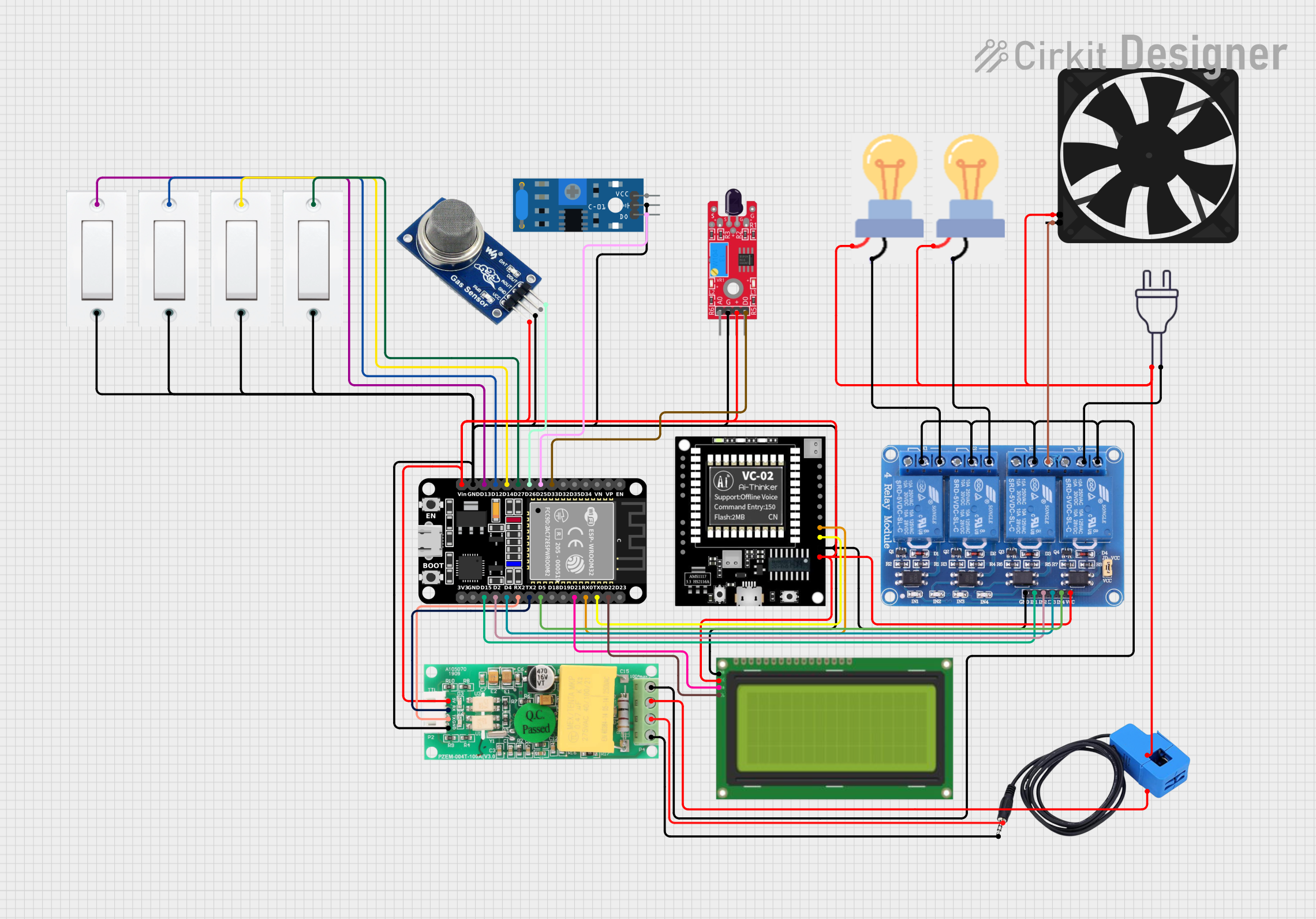 Open Project in Cirkit Designer
Explore Projects Built with CT PZEM-004T 100A
Open Project in Cirkit DesignerOpen Project in Cirkit DesignerOpen Project in Cirkit DesignerOpen Project in Cirkit DesignerCommon Applications
- Home energy monitoring systems
- Industrial equipment power usage tracking
- Renewable energy systems (e.g., solar inverters)
- Smart home automation projects
- Electrical load analysis and diagnostics
Technical Specifications
Below are the key technical details of the CT PZEM-004T 100A:
| Parameter | Specification |
|---|---|
| Voltage Measurement | 80V - 260V AC |
| Current Measurement | 0A - 100A (via external CT) |
| Power Measurement | 0W - 22kW |
| Energy Measurement | 0kWh - 9999kWh |
| Frequency Measurement | 45Hz - 65Hz |
| Communication Interface | TTL (UART) |
| Baud Rate | 9600 bps |
| Power Supply | 5V DC (external power required) |
| Accuracy | ±0.5% |
Pin Configuration
The CT PZEM-004T 100A module has a 4-pin interface for communication and power. Below is the pin configuration:
| Pin Number | Name | Description |
|---|---|---|
| 1 | VCC | 5V DC power supply input |
| 2 | GND | Ground connection |
| 3 | RX | UART Receive pin (connect to TX of microcontroller) |
| 4 | TX | UART Transmit pin (connect to RX of microcontroller) |
Usage Instructions
Connecting the CT PZEM-004T 100A
- Power Supply: Connect the
VCCpin to a 5V DC power source and theGNDpin to ground. - Communication: Use the
RXandTXpins to establish a UART connection with a microcontroller (e.g., Arduino UNO). Ensure the baud rate is set to 9600 bps. - Current Transformer (CT): Attach the included current transformer (CT) to the load wire you wish to monitor. Ensure the CT is properly clamped around a single conductor of the AC line.
- Voltage Measurement: Connect the voltage input terminals of the module to the AC line you want to monitor. Be cautious when working with high voltages.
Important Considerations
- Safety: Always ensure proper insulation and avoid direct contact with live AC wires.
- Calibration: The module is pre-calibrated, but you can recalibrate it if necessary using the manufacturer's instructions.
- Load Type: This module is designed for AC loads only and cannot measure DC circuits.
- UART Logic Levels: The module operates at 5V logic levels. If using a 3.3V microcontroller, use a level shifter.
Example: Using with Arduino UNO
Below is an example code snippet to interface the CT PZEM-004T 100A with an Arduino UNO:
#include <SoftwareSerial.h>

// Define RX and TX pins for communication with PZEM-004T
SoftwareSerial pzemSerial(10, 11); // RX = Pin 10, TX = Pin 11

// PZEM-004T communication commands
byte readVoltage[] = {0xB0, 0xC0, 0xA8, 0x01, 0x01, 0x00, 0x1A};
byte response[7];

void setup() {
  Serial.begin(9600);          // Initialize Serial Monitor
  pzemSerial.begin(9600);      // Initialize PZEM-004T communication
  Serial.println("PZEM-004T Energy Meter Example");
}

void loop() {
  // Send voltage read command to PZEM-004T
  pzemSerial.write(readVoltage, sizeof(readVoltage));
  delay(100); // Wait for response

  // Read response from PZEM-004T
  if (pzemSerial.available() >= 7) {
    for (int i = 0; i < 7; i++) {
      response[i] = pzemSerial.read();
    }

    // Extract voltage value from response
    float voltage = (response[3] << 8 | response[4]) / 10.0;
    Serial.print("Voltage: ");
    Serial.print(voltage);
    Serial.println(" V");
  }

  delay(1000); // Wait 1 second before next reading
}
Notes on the Code
- The example demonstrates how to read voltage from the PZEM-004T module.
- Ensure the
RXandTXpins of the Arduino are connected to theTXandRXpins of the module, respectively. - Use a software serial library to avoid conflicts with the Arduino's hardware serial port.
Troubleshooting and FAQs
Common Issues
No Data Received:
- Ensure the
RXandTXpins are correctly connected. - Verify the baud rate is set to 9600 bps.
- Check the power supply to the module.
- Ensure the
Incorrect Readings:
- Ensure the current transformer (CT) is properly clamped around the load wire.
- Verify the voltage input connections are secure and correct.
Module Not Responding:
- Check for loose connections or damaged wires.
- Ensure the module is powered with a stable 5V DC supply.
FAQs
Q: Can the PZEM-004T measure DC circuits?
A: No, the module is designed for AC circuits only.
Q: How do I reset the energy reading to zero?
A: The energy reading can be reset using specific UART commands. Refer to the manufacturer's documentation for details.
Q: Can I use this module with a 3.3V microcontroller?
A: Yes, but you will need a level shifter to convert the UART logic levels from 5V to 3.3V.
Q: Is the module safe to use with high voltage?
A: Yes, but always follow proper safety precautions and ensure all connections are insulated.