How to Use MAX7219 8x8 LED Matrix: Examples, Pinouts, and Specs
Introduction
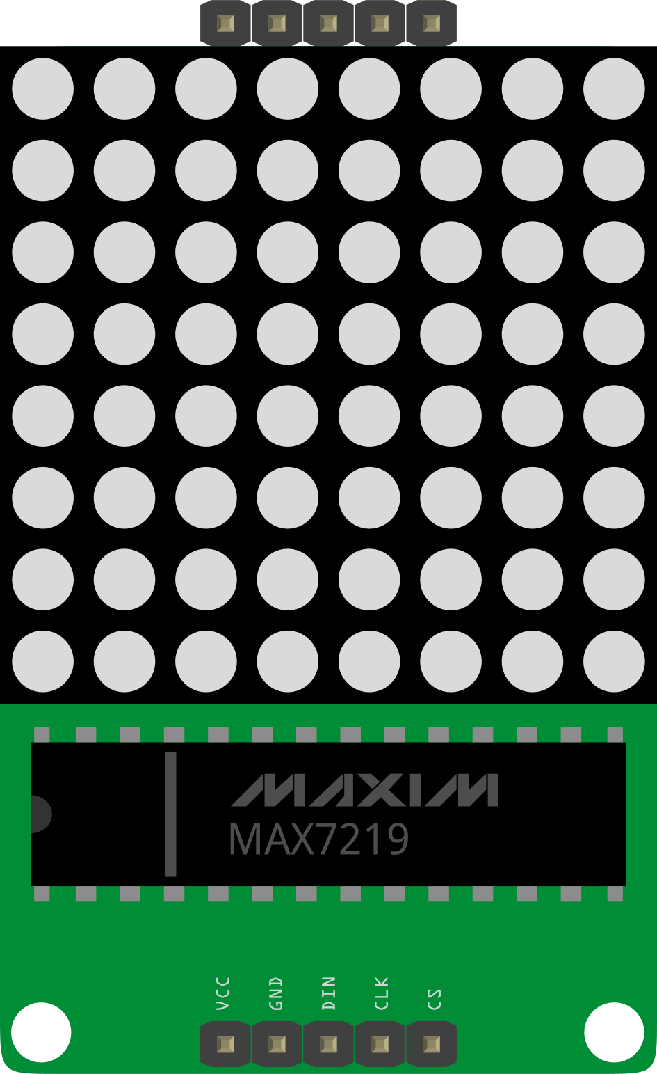
The MAX7219 is a compact, serial input/output common-cathode display driver designed to control up to 64 individual LEDs in an 8x8 matrix configuration. It simplifies the process of driving LED displays by handling multiplexing internally, reducing the need for external components. The MAX7219 communicates via a simple Serial Peripheral Interface (SPI), making it easy to integrate with microcontrollers like Arduino.
Explore Projects Built with MAX7219 8x8 LED Matrix

Explore Projects Built with MAX7219 8x8 LED Matrix
Common Applications and Use Cases
- 8x8 LED matrix displays for text, symbols, or animations
- Digital clocks and counters
- Scoreboards and status indicators
- Embedded systems requiring compact LED control
- DIY electronics projects and prototyping
Technical Specifications
Key Technical Details
- Operating Voltage: 4.0V to 5.5V
- Maximum Current per Segment: 40mA
- Maximum Current per Digit: 320mA
- Communication Protocol: SPI (Serial Peripheral Interface)
- LED Matrix Size: 8x8 (64 LEDs)
- Operating Temperature: -40°C to +85°C
- Package Type: 24-pin DIP, SO, or QFN
Pin Configuration and Descriptions
The MAX7219 has 24 pins. Below is the pin configuration:
| Pin Number | Pin Name | Description |
|---|---|---|
| 1 | DIG 0 | Digit 0 (Row 0 of the LED matrix) |
| 2 | DIG 1 | Digit 1 (Row 1 of the LED matrix) |
| 3 | DIG 2 | Digit 2 (Row 2 of the LED matrix) |
| 4 | DIG 3 | Digit 3 (Row 3 of the LED matrix) |
| 5 | DIG 4 | Digit 4 (Row 4 of the LED matrix) |
| 6 | DIG 5 | Digit 5 (Row 5 of the LED matrix) |
| 7 | DIG 6 | Digit 6 (Row 6 of the LED matrix) |
| 8 | DIG 7 | Digit 7 (Row 7 of the LED matrix) |
| 9 | GND | Ground connection |
| 10 | DOUT | Serial data output (for cascading multiple MAX7219 chips) |
| 11 | LOAD (CS) | Chip select (active low) |
| 12 | CLK | Serial clock input |
| 13 | DIN | Serial data input |
| 14 | V+ | Positive supply voltage |
| 15 | SEG DP | Segment DP (Decimal Point) |
| 16-23 | SEG A-G | Segment A to G (Columns of the LED matrix) |
| 24 | ISET | Current setting resistor pin (connect to a resistor to set LED current limit) |
Usage Instructions
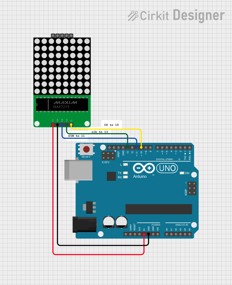
How to Use the MAX7219 in a Circuit
- Power Supply: Connect the V+ pin to a 5V power supply and the GND pin to ground.
- LED Matrix Connection: Connect the DIG pins (DIG 0 to DIG 7) to the rows of the LED matrix and the SEG pins (SEG A to SEG DP) to the columns.
- SPI Communication: Connect the DIN, CLK, and LOAD pins to the microcontroller's SPI pins:
- DIN to MOSI (Master Out Slave In)
- CLK to SCK (Serial Clock)
- LOAD to a digital pin (used as Chip Select)
- Current Limiting Resistor: Connect a resistor (typically 10kΩ) between the ISET pin and GND to set the LED current.
- Programming: Use SPI commands to send data to the MAX7219 to control the LED matrix.
Important Considerations and Best Practices
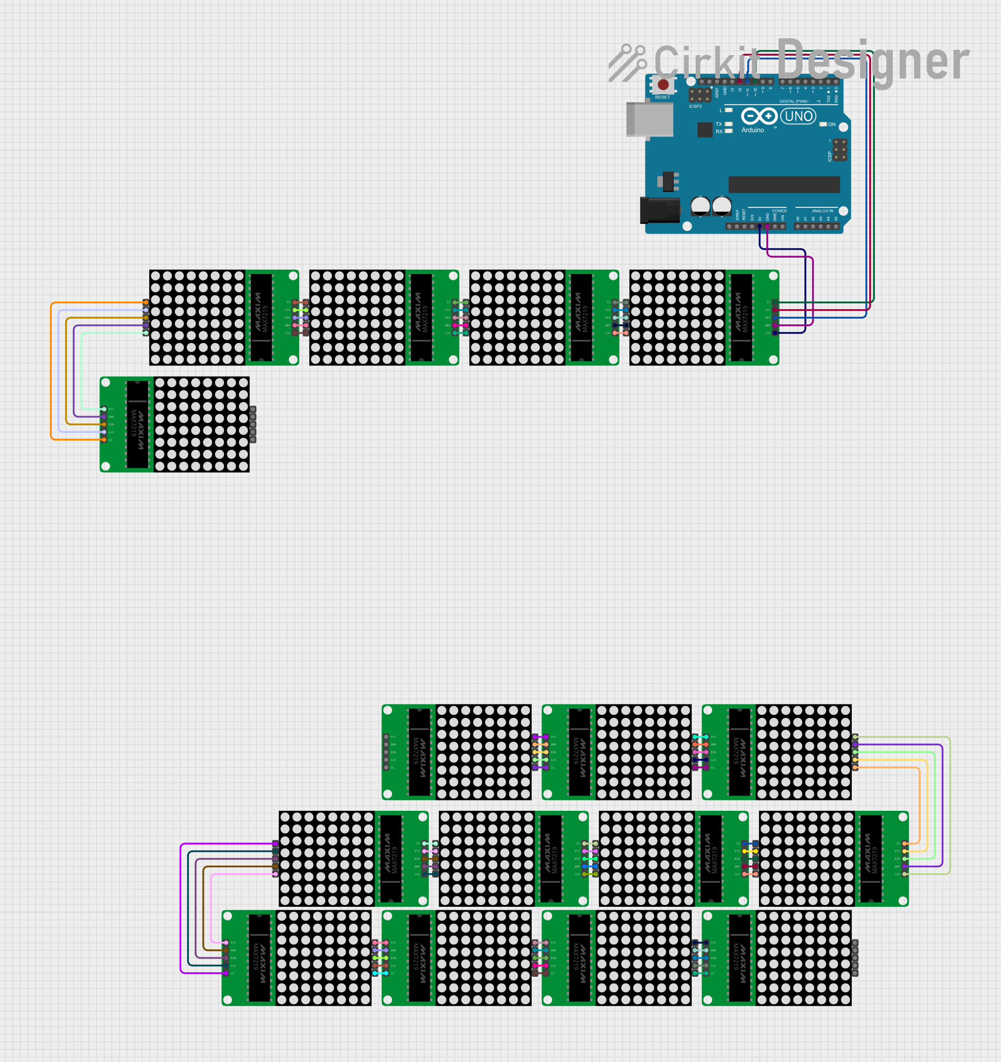
- Cascading Multiple MAX7219 Chips: To control multiple LED matrices, connect the DOUT pin of one MAX7219 to the DIN pin of the next.
- Resistor Selection: The value of the resistor on the ISET pin determines the brightness of the LEDs. Use a higher resistance for lower brightness.
- Decoupling Capacitor: Place a 10µF electrolytic capacitor and a 0.1µF ceramic capacitor across the V+ and GND pins to stabilize the power supply.
- Avoid Overloading: Ensure the total current does not exceed the MAX7219's maximum ratings to prevent damage.
Example Code for Arduino UNO
Below is an example of how to control an 8x8 LED matrix using the MAX7219 and Arduino UNO:
#include <SPI.h> // Include the SPI library

#define LOAD_PIN 10 // Define the LOAD (CS) pin

// Function to send data to the MAX7219
void sendToMax7219(byte address, byte data) {
  digitalWrite(LOAD_PIN, LOW); // Begin communication
  SPI.transfer(address);      // Send the register address
  SPI.transfer(data);         // Send the data
  digitalWrite(LOAD_PIN, HIGH); // End communication
}

void setup() {
  pinMode(LOAD_PIN, OUTPUT); // Set LOAD pin as output
  SPI.begin();               // Initialize SPI communication

  // Initialize the MAX7219
  sendToMax7219(0x09, 0x00); // Decode mode: No decode
  sendToMax7219(0x0A, 0x08); // Intensity: Medium brightness
  sendToMax7219(0x0B, 0x07); // Scan limit: Display all 8 digits
  sendToMax7219(0x0C, 0x01); // Shutdown register: Normal operation
  sendToMax7219(0x0F, 0x00); // Display test: Off
}

void loop() {
  // Example: Light up a single LED in the matrix
  sendToMax7219(1, 0b10000000); // Light up the first row, first column
  delay(500);                   // Wait for 500ms
  sendToMax7219(1, 0b00000000); // Turn off the LED
  delay(500);                   // Wait for 500ms
}
Troubleshooting and FAQs
Common Issues and Solutions
LEDs Not Lighting Up:
- Check the power supply connections (V+ and GND).
- Verify the SPI connections (DIN, CLK, and LOAD).
- Ensure the ISET resistor is properly connected.
Incorrect LED Behavior:
- Double-check the wiring between the MAX7219 and the LED matrix.
- Ensure the correct SPI commands are being sent.
Dim LEDs:
- Adjust the ISET resistor value to increase brightness.
- Verify the power supply voltage is within the recommended range.
Multiple MAX7219 Chips Not Working:
- Ensure the DOUT pin of one chip is connected to the DIN pin of the next.
- Verify that the SPI commands are sent in the correct order.
FAQs
Q: Can I use the MAX7219 with a 3.3V microcontroller?
A: Yes, but you need to ensure the logic levels are compatible. Use a level shifter if necessary.
Q: How many MAX7219 chips can I cascade?
A: Theoretically, you can cascade up to 8 chips, but the practical limit depends on the driving capability of your microcontroller and the power supply.
Q: Can I control individual LEDs in the matrix?
A: Yes, by sending the appropriate data to the MAX7219, you can control each LED individually.
Q: What happens if I exceed the maximum current ratings?
A: Exceeding the current ratings can damage the MAX7219 or the LEDs. Always stay within the specified limits.