How to Use SBUS Reciever: Examples, Pinouts, and Specs
Introduction
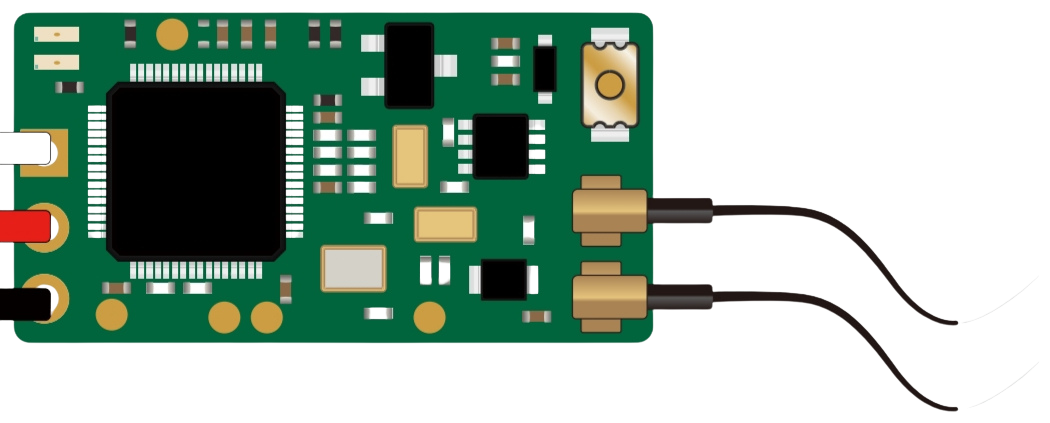
The SBUS Receiver is a device designed to receive signals from a transmitter using the SBUS protocol. This protocol is widely used in remote control systems for model aircraft, drones, and other RC (radio-controlled) applications. The SBUS protocol allows for the transmission of multiple control channels (up to 16 or more) over a single signal wire, providing low-latency communication and efficient use of resources.
Explore Projects Built with SBUS Reciever

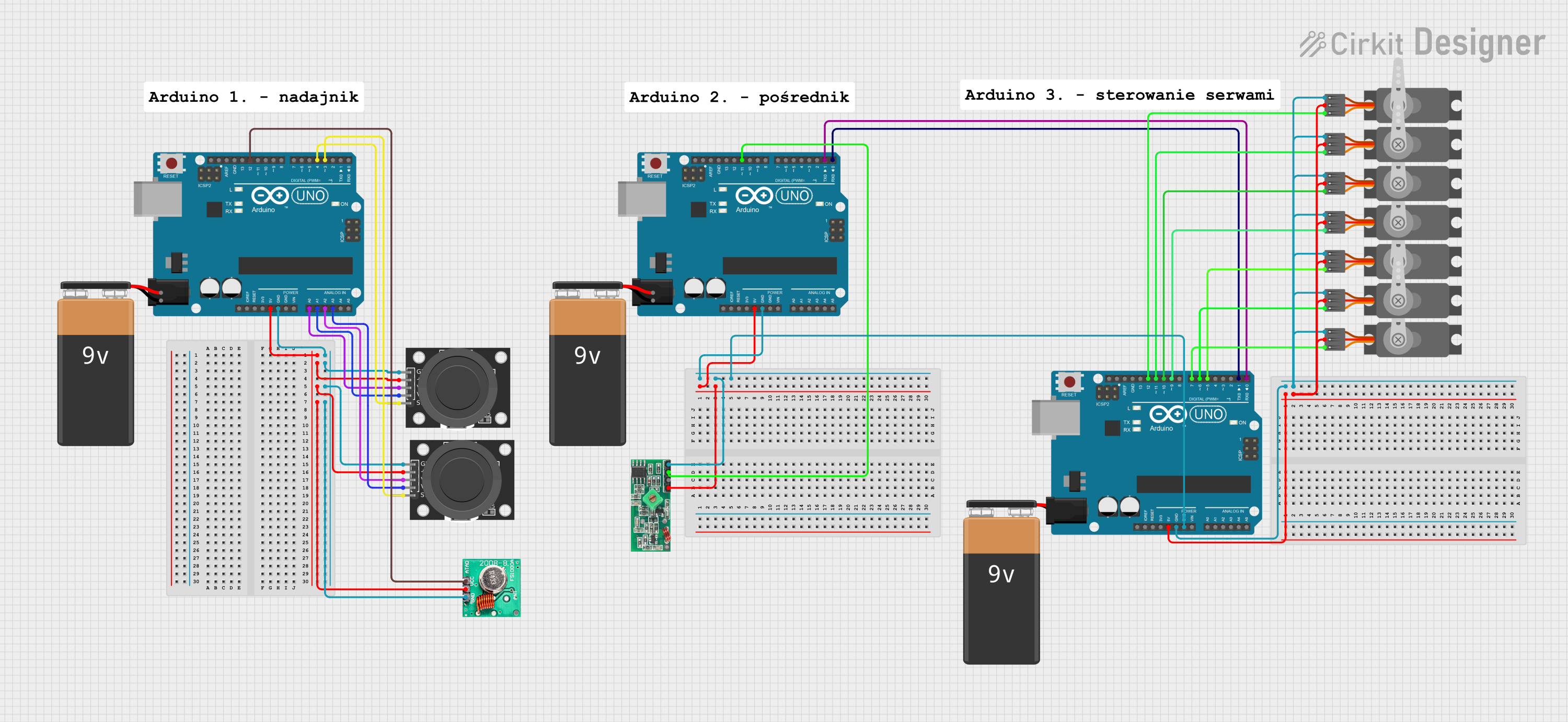
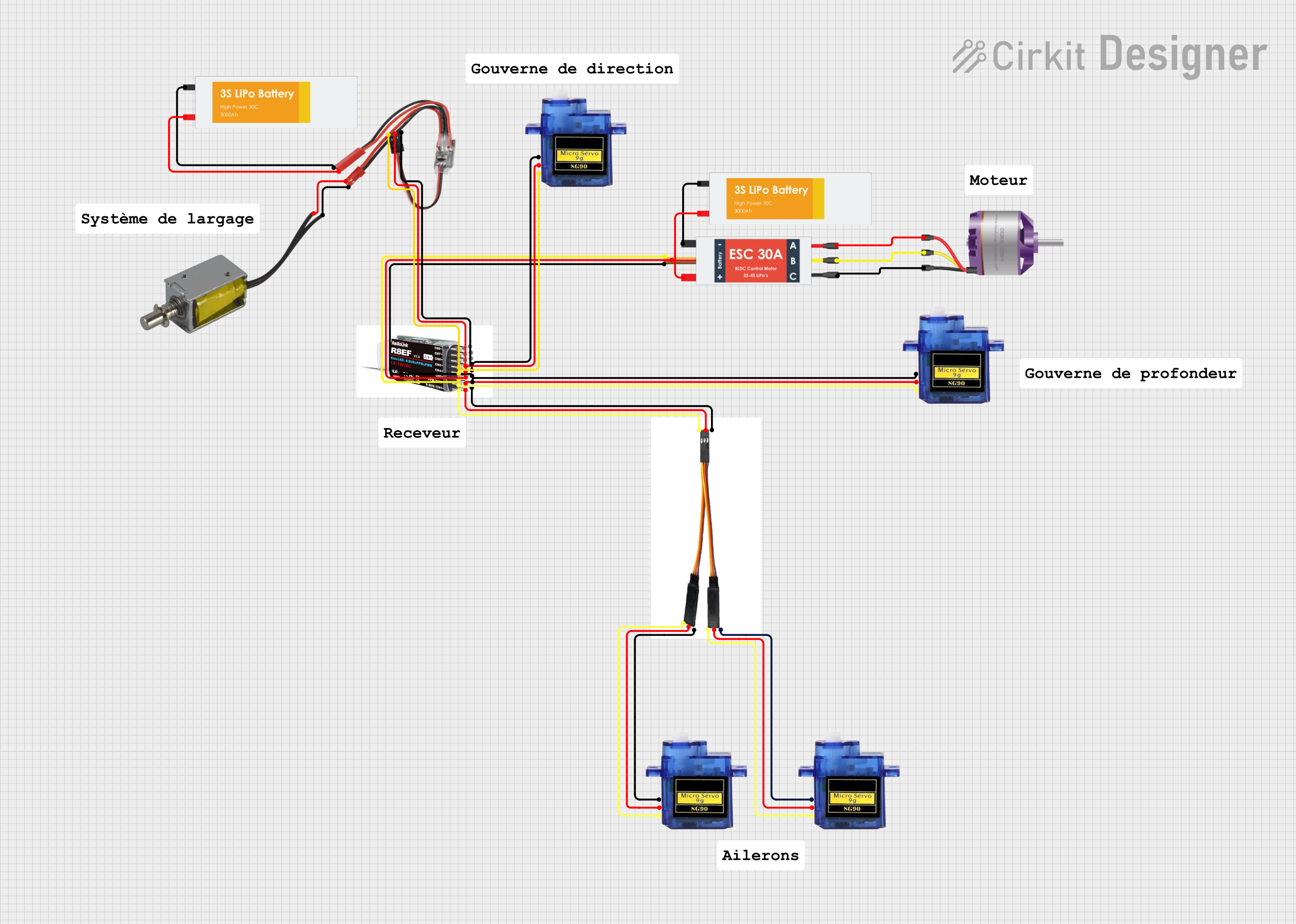

Explore Projects Built with SBUS Reciever
Common Applications and Use Cases
- Remote control of drones, quadcopters, and RC planes
- Model cars and boats
- Robotics and automation systems requiring multi-channel control
- Integration with flight controllers and microcontrollers for advanced control systems
Technical Specifications
The SBUS Receiver is designed to work seamlessly with SBUS-compatible transmitters and flight controllers. Below are the key technical details:
General Specifications
| Parameter | Value |
|---|---|
| Protocol | SBUS |
| Number of Channels | Up to 16 |
| Operating Voltage | 3.3V to 5.0V |
| Signal Output | Inverted Serial (UART) |
| Communication Speed | 100,000 baud (fixed) |
| Latency | ~3ms |
| Connector Type | 3-pin (Signal, VCC, GND) |
| Dimensions | Varies by model (e.g., 25x15mm) |
| Weight | Typically <10g |
Pin Configuration and Descriptions
| Pin Name | Description |
|---|---|
| Signal | SBUS signal output (inverted UART) |
| VCC | Power input (3.3V to 5.0V) |
| GND | Ground connection |
Usage Instructions
How to Use the SBUS Receiver in a Circuit
Connect the Receiver to a Power Source:
- Connect the
VCCpin to a 3.3V or 5.0V power source. - Connect the
GNDpin to the ground of your circuit.
- Connect the
Connect the Signal Pin:
- Connect the
Signalpin to the SBUS input of your flight controller or microcontroller. - Ensure that the microcontroller or flight controller supports inverted UART signals. If not, use an inverter circuit or software-based signal inversion.
- Connect the
Bind the Receiver to the Transmitter:
- Follow the specific binding procedure for your SBUS receiver and transmitter. This typically involves pressing a bind button on the receiver while powering it on.
Configure the Flight Controller or Microcontroller:
- Set the communication protocol to SBUS in your flight controller or microcontroller software.
- Ensure the baud rate is set to 100,000.
Important Considerations and Best Practices
- Signal Inversion: SBUS uses an inverted UART signal. If your microcontroller does not support inverted signals, you may need to use a hardware inverter or configure software-based inversion.
- Power Supply: Ensure the receiver is powered within its operating voltage range (3.3V to 5.0V). Exceeding this range may damage the receiver.
- Antenna Placement: For optimal signal reception, position the receiver's antenna away from sources of interference, such as motors or ESCs (Electronic Speed Controllers).
- Failsafe Configuration: Configure the failsafe settings on your transmitter to ensure safe operation in case of signal loss.
Example: Connecting to an Arduino UNO
To use the SBUS Receiver with an Arduino UNO, you will need to invert the SBUS signal. This can be done using a hardware inverter or by modifying the Arduino's UART library. Below is an example code snippet for reading SBUS data:
#include <SoftwareSerial.h>

// Define the SBUS signal pin
#define SBUS_PIN 10

// Create a SoftwareSerial object for SBUS communication
SoftwareSerial sbusSerial(SBUS_PIN, -1); // RX pin, no TX pin

void setup() {
  // Initialize the serial monitor
  Serial.begin(9600);
  // Initialize the SBUS communication at 100,000 baud
  sbusSerial.begin(100000);
  Serial.println("SBUS Receiver Initialized");
}

void loop() {
  // Check if data is available from the SBUS receiver
  if (sbusSerial.available()) {
    // Read and print the incoming SBUS data
    uint8_t sbusData = sbusSerial.read();
    Serial.print("SBUS Data: ");
    Serial.println(sbusData, HEX);
  }
}
Note: The above code assumes the use of a hardware inverter for the SBUS signal. If you are using a software-based inversion library, modify the code accordingly.
Troubleshooting and FAQs
Common Issues and Solutions
No Signal from the Receiver:
- Ensure the receiver is properly bound to the transmitter.
- Verify that the power supply voltage is within the specified range (3.3V to 5.0V).
- Check the signal connection and ensure it is connected to the correct pin on the flight controller or microcontroller.
Data Corruption or Unreadable Data:
- Confirm that the baud rate is set to 100,000 in your microcontroller or flight controller software.
- Ensure the SBUS signal is properly inverted if required by your hardware.
Intermittent Signal Loss:
- Check the antenna placement and ensure it is not obstructed or too close to sources of interference.
- Verify that the transmitter and receiver are within the specified range.
Failsafe Not Working:
- Configure the failsafe settings on your transmitter to ensure proper behavior in case of signal loss.
FAQs
Q: Can I use the SBUS Receiver with a 3.3V microcontroller?
A: Yes, the SBUS Receiver operates within a voltage range of 3.3V to 5.0V, making it compatible with 3.3V microcontrollers.
Q: Do I need a hardware inverter for the SBUS signal?
A: It depends on your microcontroller. Some microcontrollers support inverted UART signals natively, while others require a hardware inverter or software-based inversion.
Q: How many channels can the SBUS Receiver handle?
A: The SBUS protocol supports up to 16 channels, with some receivers offering additional channels for telemetry or auxiliary functions.
Q: Can I use the SBUS Receiver with non-SBUS transmitters?
A: No, the SBUS Receiver is specifically designed to work with SBUS-compatible transmitters.
By following this documentation, you can effectively integrate and troubleshoot the SBUS Receiver in your projects.