How to Use Contactor Chint 20A: Examples, Pinouts, and Specs
Introduction
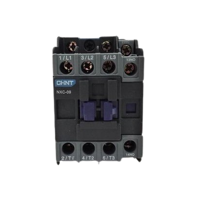
The CHINT NXC-09A Contactor is an electrically controlled switch designed for industrial and commercial applications. It is primarily used to control and switch power circuits, enabling the automation of high-power devices such as motors, heaters, and lighting systems. With a current rating of 20A, this contactor is ideal for medium-load applications, ensuring reliable performance and durability.
Explore Projects Built with Contactor Chint 20A


Explore Projects Built with Contactor Chint 20A
Common Applications
- Motor control in industrial machinery
- HVAC systems
- Lighting control in commercial buildings
- Power distribution systems
- Automation systems in factories
Technical Specifications
Key Technical Details
| Parameter | Value |
|---|---|
| Manufacturer | CHINT |
| Model Number | NXC-09A |
| Rated Current (AC-3) | 20A |
| Rated Voltage | 690V AC |
| Coil Voltage Options | 24V AC/DC, 110V AC, 220V AC |
| Number of Poles | 3 |
| Mechanical Durability | 10 million operations |
| Electrical Durability | 1 million operations |
| Operating Temperature | -5°C to +40°C |
| Mounting Type | DIN Rail or Screw Mount |
| Standards Compliance | IEC 60947-4-1, CE, CCC |
Pin Configuration and Descriptions
The NXC-09A contactor has a straightforward terminal layout for power and control connections. Below is the pin configuration:
Power Terminals
| Terminal Label | Description |
|---|---|
| L1, L2, L3 | Input terminals for three-phase power |
| T1, T2, T3 | Output terminals for load connection |
Control Terminals
| Terminal Label | Description |
|---|---|
| A1, A2 | Coil terminals for control voltage |
| NO (Normally Open) | Auxiliary contact for control circuits |
| NC (Normally Closed) | Auxiliary contact for control circuits |
Usage Instructions
How to Use the Contactor in a Circuit
Power Connections:
- Connect the three-phase power supply to the input terminals (L1, L2, L3).
- Connect the load (e.g., motor) to the output terminals (T1, T2, T3).
Control Circuit:
- Connect the control voltage to the coil terminals (A1 and A2). Ensure the voltage matches the coil rating (e.g., 24V AC/DC, 110V AC, or 220V AC).
- Use the auxiliary contacts (NO/NC) for additional control logic, such as interlocking or feedback.
Mounting:
- Secure the contactor to a DIN rail or use screws for panel mounting.
Testing:
- After wiring, test the circuit by energizing the coil. The contactor should click into position, connecting the power circuit.
Important Considerations and Best Practices
- Voltage Matching: Ensure the control voltage matches the coil rating to avoid damage.
- Overload Protection: Use an appropriate overload relay in series with the contactor to protect the load.
- Wiring: Use wires with appropriate gauge to handle the rated current (20A).
- Environment: Install the contactor in a clean, dry environment within the specified temperature range (-5°C to +40°C).
- Maintenance: Periodically inspect the contactor for wear and clean the contacts to ensure reliable operation.
Example: Using the Contactor with an Arduino UNO
The CHINT NXC-09A can be controlled using an Arduino UNO by energizing its coil with a relay module. Below is an example circuit and code:
Circuit Description
- Use a 5V relay module to interface the Arduino with the contactor's coil.
- The Arduino controls the relay, which in turn energizes the contactor's coil.
Arduino Code
// Define the pin connected to the relay module
const int relayPin = 7;

void setup() {
  // Set the relay pin as an output
  pinMode(relayPin, OUTPUT);
  // Ensure the relay is off at startup
  digitalWrite(relayPin, LOW);
}

void loop() {
  // Turn on the relay to energize the contactor
  digitalWrite(relayPin, HIGH);
  delay(5000); // Keep the contactor on for 5 seconds

  // Turn off the relay to de-energize the contactor
  digitalWrite(relayPin, LOW);
  delay(5000); // Wait for 5 seconds before repeating
}
Troubleshooting and FAQs
Common Issues and Solutions
| Issue | Possible Cause | Solution |
|---|---|---|
| Contactor does not energize | Incorrect control voltage | Verify the coil voltage and wiring. |
| Excessive noise during operation | Worn or dirty contacts | Inspect and clean the contacts. |
| Overheating | Overcurrent or poor ventilation | Check the load current and ensure proper ventilation. |
| Frequent tripping | Incorrect overload relay settings | Adjust the overload relay to match the load. |
FAQs
Can the NXC-09A be used for single-phase loads?
- Yes, connect the single-phase load to one of the poles and leave the other poles unused.
What is the maximum wire size for the terminals?
- The terminals can accommodate wires up to 10mm².
Can the contactor be mounted horizontally?
- Yes, the NXC-09A supports both vertical and horizontal mounting orientations.
How do I know if the contactor is faulty?
- If the coil is energized but the contacts do not close, the contactor may be faulty and should be replaced.
By following this documentation, users can effectively integrate the CHINT NXC-09A contactor into their systems for reliable and efficient operation.