How to Use IN4007: Examples, Pinouts, and Specs
Introduction
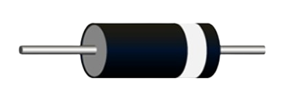
The IN4007 is a silicon rectifier diode designed for general-purpose applications. It is capable of withstanding a maximum reverse voltage of 1000V and can handle a forward current of up to 1A. This diode is widely used in power supply circuits for rectification, voltage regulation, and protection against reverse polarity. Its robust design and reliability make it a popular choice in both hobbyist and industrial electronics projects.
Explore Projects Built with IN4007

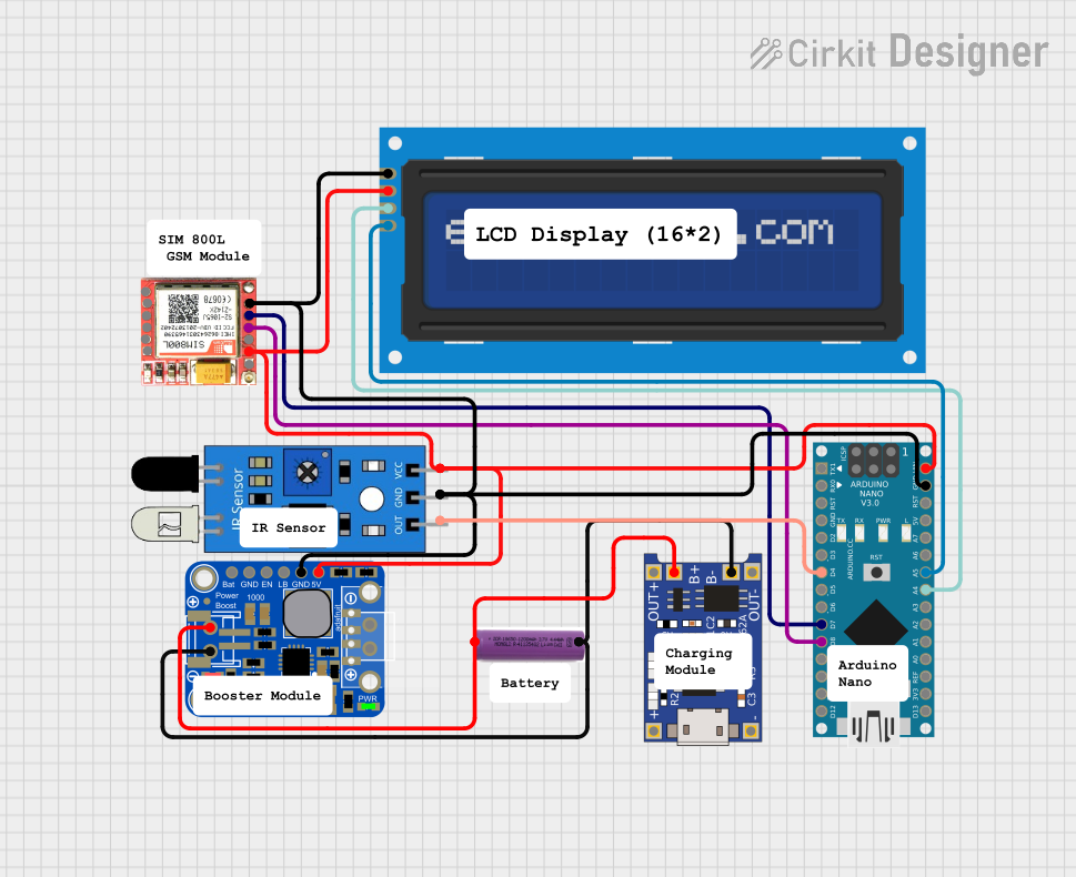


Explore Projects Built with IN4007
Common Applications
- AC to DC rectification in power supplies
- Reverse polarity protection in circuits
- Voltage clamping and freewheeling in inductive loads
- General-purpose diode applications in low- and medium-power circuits
Technical Specifications
Below are the key technical details of the IN4007 diode:
| Parameter | Value |
|---|---|
| Maximum Reverse Voltage | 1000V |
| Maximum Forward Current | 1A |
| Peak Surge Current | 30A (8.3ms single half-sine) |
| Forward Voltage Drop | 1.1V (at 1A forward current) |
| Reverse Current | 5µA (at 25°C, 1000V) |
| Operating Temperature | -65°C to +150°C |
| Package Type | DO-41 |
Pin Configuration
The IN4007 diode has two terminals:
| Pin | Description |
|---|---|
| Anode | Positive terminal (current enters) |
| Cathode | Negative terminal (current exits) |
The cathode is typically marked with a silver or white band on the diode body.
Usage Instructions
How to Use the IN4007 in a Circuit
- Rectification: To convert AC to DC, connect the IN4007 in a bridge rectifier configuration or as a single diode rectifier. Ensure the cathode is connected to the positive side of the load.
- Reverse Polarity Protection: Place the IN4007 in series with the power supply input. The cathode should face the positive voltage source to block reverse current.
- Voltage Clamping: Use the IN4007 in parallel with sensitive components to protect them from voltage spikes.
Important Considerations
- Current Handling: Ensure the forward current does not exceed 1A to prevent overheating or damage.
- Heat Dissipation: If operating near the maximum current rating, consider adding a heatsink or ensuring proper ventilation.
- Reverse Voltage: Do not exceed the maximum reverse voltage of 1000V to avoid breakdown.
- Polarity: Always verify the orientation of the diode before connecting it to the circuit. The cathode is marked with a band.
Example: Using IN4007 with Arduino UNO
The IN4007 can be used to protect an Arduino UNO from reverse polarity. Below is an example circuit and code:
Circuit Description
- Connect the IN4007 in series with the Arduino's power input (VIN pin).
- The cathode (marked with a band) should face the VIN pin, and the anode should connect to the positive terminal of the power source.
Arduino Code Example
// Example code to blink an LED connected to pin 13
// Ensure the IN4007 diode is protecting the Arduino's power input

void setup() {
  pinMode(13, OUTPUT); // Set pin 13 as an output
}

void loop() {
  digitalWrite(13, HIGH); // Turn the LED on
  delay(1000);            // Wait for 1 second
  digitalWrite(13, LOW);  // Turn the LED off
  delay(1000);            // Wait for 1 second
}
Troubleshooting and FAQs
Common Issues
Diode Overheating:
- Cause: Exceeding the maximum forward current of 1A.
- Solution: Reduce the load current or use a diode with a higher current rating.
No Output Voltage in Rectifier Circuit:
- Cause: Incorrect diode orientation.
- Solution: Verify the anode and cathode connections. The cathode should face the positive side of the load.
High Reverse Leakage Current:
- Cause: Operating at high temperatures or exceeding reverse voltage rating.
- Solution: Ensure the diode operates within its specified temperature and voltage limits.
Diode Fails to Conduct:
- Cause: Faulty or damaged diode.
- Solution: Test the diode with a multimeter and replace if necessary.
FAQs
Q: Can the IN4007 be used for high-frequency applications?
A: No, the IN4007 is not suitable for high-frequency applications due to its relatively slow switching speed. Use a fast recovery or Schottky diode for such purposes.
Q: What is the difference between the IN4007 and other diodes in the 1N400x series?
A: The primary difference is the maximum reverse voltage rating. The IN4007 has the highest rating (1000V) in the series, making it suitable for higher voltage applications.
Q: Can I use the IN4007 for AC voltage rectification?
A: Yes, the IN4007 is commonly used for rectifying AC voltage in power supply circuits. Ensure the voltage and current ratings are within the diode's limits.
Q: How do I test if my IN4007 diode is working?
A: Use a multimeter in diode mode. Connect the positive probe to the anode and the negative probe to the cathode. A forward voltage drop of approximately 0.7V should be observed. Reverse the probes to check for no conduction in the reverse direction.