How to Use BMA400 : Examples, Pinouts, and Specs
Introduction
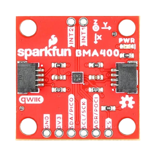
The BMA400 is a low-power, 3-axis accelerometer manufactured by Sparkfun. It is specifically designed for battery-operated devices, offering exceptional energy efficiency while maintaining high accuracy and low noise performance. The BMA400 features a digital output and is optimized for motion sensing applications, making it ideal for use in wearables, smart home devices, and portable electronics.
Explore Projects Built with BMA400


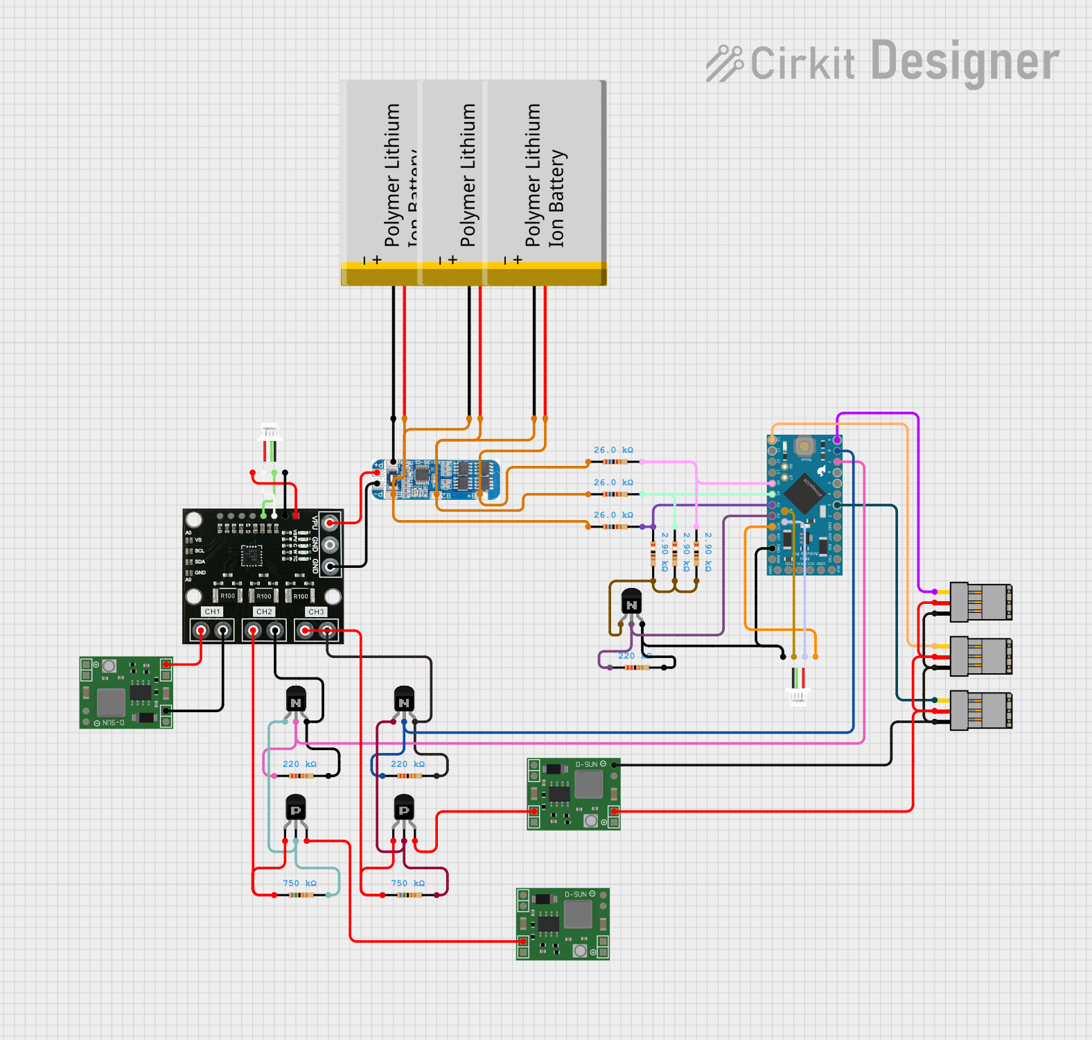

Explore Projects Built with BMA400
Common Applications and Use Cases
- Fitness trackers and wearables
- Smart home devices (e.g., motion detection for lighting or security systems)
- Portable electronics with motion-based controls
- Vibration monitoring and tilt detection
- Step counting and activity recognition
Technical Specifications
The BMA400 is a versatile accelerometer with the following key technical details:
| Parameter | Value |
|---|---|
| Operating Voltage | 1.8V to 3.6V |
| Current Consumption | 14 µA (low-power mode) |
| Measurement Range | ±2g, ±4g, ±8g, ±16g |
| Output Data Rate (ODR) | 0.78 Hz to 800 Hz |
| Communication Interface | I²C and SPI |
| Resolution | 12-bit |
| Operating Temperature Range | -40°C to +85°C |
| Dimensions | 2.0 mm x 2.0 mm x 0.95 mm |
Pin Configuration and Descriptions
The BMA400 comes in a compact package with the following pin configuration:
| Pin Name | Pin Number | Description |
|---|---|---|
| VDD | 1 | Power supply input (1.8V to 3.6V) |
| GND | 2 | Ground |
| SCL/SPC | 3 | I²C clock line / SPI clock |
| SDA/SDI/SDO | 4 | I²C data line / SPI data input/output |
| CS | 5 | Chip select for SPI (active low) |
| INT1 | 6 | Interrupt 1 output |
| INT2 | 7 | Interrupt 2 output |
| NC | 8 | Not connected (leave floating) |
Usage Instructions
How to Use the BMA400 in a Circuit
- Power Supply: Connect the VDD pin to a 1.8V to 3.6V power source and the GND pin to ground.
- Communication Interface: Choose between I²C or SPI for communication:
- For I²C, connect the SCL and SDA pins to the corresponding lines on your microcontroller.
- For SPI, connect the SCL/SPC, SDA/SDI/SDO, and CS pins to the appropriate SPI lines.
- Interrupts: Use the INT1 and INT2 pins to configure motion-based interrupts if needed.
- Pull-Up Resistors: For I²C communication, ensure pull-up resistors (typically 4.7 kΩ) are connected to the SCL and SDA lines.
- Bypass Capacitor: Place a 0.1 µF capacitor close to the VDD pin for power supply decoupling.
Important Considerations and Best Practices
- Voltage Levels: Ensure the microcontroller's I/O voltage levels are compatible with the BMA400's operating voltage.
- Mounting Orientation: Properly align the BMA400 on the PCB to match the desired axis of measurement.
- Noise Reduction: Use a clean power supply and proper grounding to minimize noise in measurements.
- Interrupt Configuration: Configure the interrupt pins to detect specific motion events, such as free-fall or step counting.
Example Code for Arduino UNO
Below is an example of how to interface the BMA400 with an Arduino UNO using I²C communication:
#include <Wire.h> // Include the Wire library for I²C communication

#define BMA400_ADDRESS 0x14 // Default I²C address of the BMA400

void setup() {
  Wire.begin(); // Initialize I²C communication
  Serial.begin(9600); // Start serial communication for debugging

  // Initialize the BMA400
  Wire.beginTransmission(BMA400_ADDRESS);
  Wire.write(0x7D); // Write to the power control register
  Wire.write(0x04); // Set the accelerometer to normal mode
  Wire.endTransmission();

  Serial.println("BMA400 initialized.");
}

void loop() {
  // Request accelerometer data
  Wire.beginTransmission(BMA400_ADDRESS);
  Wire.write(0x04); // Address of the X-axis LSB register
  Wire.endTransmission();
  Wire.requestFrom(BMA400_ADDRESS, 6); // Request 6 bytes (X, Y, Z data)

  if (Wire.available() == 6) {
    int16_t x = Wire.read() | (Wire.read() << 8); // Combine LSB and MSB
    int16_t y = Wire.read() | (Wire.read() << 8);
    int16_t z = Wire.read() | (Wire.read() << 8);

    // Print the accelerometer data
    Serial.print("X: ");
    Serial.print(x);
    Serial.print(" Y: ");
    Serial.print(y);
    Serial.print(" Z: ");
    Serial.println(z);
  }

  delay(500); // Wait for 500ms before the next reading
}
Troubleshooting and FAQs
Common Issues and Solutions
No Communication with the BMA400
- Solution: Verify the I²C or SPI connections and ensure the correct address (0x14) is used for I²C.
- Tip: Check for proper pull-up resistors on the I²C lines.
Incorrect or No Data Output
- Solution: Ensure the BMA400 is properly initialized and configured for the desired mode.
- Tip: Double-check the power supply voltage and bypass capacitor placement.
High Noise in Measurements
- Solution: Use a clean power supply and ensure proper grounding.
- Tip: Enable the BMA400's built-in low-pass filter to reduce noise.
Interrupts Not Triggering
- Solution: Verify the interrupt configuration and ensure the INT1/INT2 pins are connected.
- Tip: Check the interrupt threshold and duration settings in the BMA400's registers.
FAQs
Q: Can the BMA400 operate at 5V?
A: No, the BMA400's maximum operating voltage is 3.6V. Use a voltage regulator or level shifter if needed.Q: How do I change the measurement range?
A: Update the range settings in the BMA400's configuration registers via I²C or SPI.Q: What is the default I²C address of the BMA400?
A: The default I²C address is 0x14.Q: Can the BMA400 detect free-fall events?
A: Yes, the BMA400 can be configured to detect free-fall and other motion events using its interrupt system.