How to Use Luxonis Y-adapter: Examples, Pinouts, and Specs
Introduction
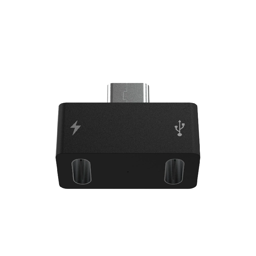
The Luxonis Y-adapter (Part ID: A00513) is a versatile electronic component designed to enable the connection of multiple devices to a single interface. This adapter is particularly useful in robotics and AI applications, where it facilitates seamless communication between sensors, cameras, and processing units. Its compact design and robust construction make it an essential tool for developers working on complex systems requiring multiple device integrations.
Explore Projects Built with Luxonis Y-adapter


Explore Projects Built with Luxonis Y-adapter
Common Applications and Use Cases
- Connecting multiple sensors (e.g., depth cameras, IMUs) to a single processing unit.
- Expanding communication interfaces in robotics platforms.
- AI and machine learning projects requiring synchronized data from multiple devices.
- Prototyping and testing multi-sensor setups in embedded systems.
Technical Specifications
Key Technical Details
- Manufacturer: Luxonis
- Part ID: A00513
- Connector Type: 4-pin JST-GH
- Voltage Rating: 3.3V to 5V (pass-through)
- Current Rating: Up to 1A per channel
- Dimensions: 30mm x 20mm x 5mm
- Weight: 5g
- Operating Temperature: -20°C to 70°C
- Material: PCB with gold-plated connectors for durability and low resistance
Pin Configuration and Descriptions
The Luxonis Y-adapter features three 4-pin JST-GH connectors: one input and two outputs. The pin configuration is as follows:
| Pin Number | Pin Name | Description | Direction |
|---|---|---|---|
| 1 | VCC | Power supply (3.3V to 5V) | Input/Output |
| 2 | GND | Ground | Input/Output |
| 3 | SCL | Serial Clock Line (I2C) | Input/Output |
| 4 | SDA | Serial Data Line (I2C) | Input/Output |
Usage Instructions
How to Use the Component in a Circuit
- Connect the Input Port: Attach the input device (e.g., a microcontroller or processing unit) to the input port of the Y-adapter using a 4-pin JST-GH cable.
- Connect the Output Ports: Attach the output devices (e.g., sensors or cameras) to the two output ports using compatible 4-pin JST-GH cables.
- Power the System: Ensure the input device provides a stable power supply (3.3V to 5V) to the Y-adapter. The adapter will pass this power to the connected output devices.
- Verify Connections: Double-check all connections to ensure proper alignment of pins (VCC, GND, SCL, SDA) to avoid damage to the devices.
- Test Communication: Use appropriate software or firmware to test communication between the input and output devices.
Important Considerations and Best Practices
- Power Supply: Ensure the total current draw of the connected devices does not exceed 1A. Use an external power source if necessary.
- Cable Length: Keep cable lengths as short as possible to minimize signal degradation, especially for high-speed I2C communication.
- Signal Integrity: Use pull-up resistors on the SCL and SDA lines if the connected devices do not have built-in pull-ups.
- Compatibility: Verify that all connected devices operate at the same voltage level (3.3V or 5V) to prevent damage.
Example: Connecting to an Arduino UNO
The Luxonis Y-adapter can be used to connect multiple I2C devices to an Arduino UNO. Below is an example Arduino sketch for reading data from two I2C sensors connected via the Y-adapter.
#include <Wire.h>

// Define I2C addresses for the two sensors
#define SENSOR1_ADDR 0x40  // Replace with the actual address of sensor 1
#define SENSOR2_ADDR 0x41  // Replace with the actual address of sensor 2

void setup() {
  Wire.begin();  // Initialize I2C communication
  Serial.begin(9600);  // Start serial communication for debugging

  // Check communication with sensor 1
  Wire.beginTransmission(SENSOR1_ADDR);
  if (Wire.endTransmission() == 0) {
    Serial.println("Sensor 1 connected successfully.");
  } else {
    Serial.println("Failed to connect to Sensor 1.");
  }

  // Check communication with sensor 2
  Wire.beginTransmission(SENSOR2_ADDR);
  if (Wire.endTransmission() == 0) {
    Serial.println("Sensor 2 connected successfully.");
  } else {
    Serial.println("Failed to connect to Sensor 2.");
  }
}

void loop() {
  // Example: Read data from both sensors and print to Serial Monitor

  // Read from Sensor 1
  Wire.requestFrom(SENSOR1_ADDR, 2);  // Request 2 bytes of data
  if (Wire.available() == 2) {
    int data1 = Wire.read() << 8 | Wire.read();  // Combine two bytes
    Serial.print("Sensor 1 Data: ");
    Serial.println(data1);
  }

  // Read from Sensor 2
  Wire.requestFrom(SENSOR2_ADDR, 2);  // Request 2 bytes of data
  if (Wire.available() == 2) {
    int data2 = Wire.read() << 8 | Wire.read();  // Combine two bytes
    Serial.print("Sensor 2 Data: ");
    Serial.println(data2);
  }

  delay(1000);  // Wait 1 second before the next read
}
Troubleshooting and FAQs
Common Issues Users Might Face
No Communication Between Devices
- Cause: Incorrect wiring or mismatched voltage levels.
- Solution: Verify all connections and ensure all devices operate at the same voltage level.
Signal Degradation or Noise
- Cause: Long cables or lack of pull-up resistors on I2C lines.
- Solution: Use shorter cables and add pull-up resistors (e.g., 4.7kΩ) to the SCL and SDA lines.
Overheating or Power Issues
- Cause: Excessive current draw from connected devices.
- Solution: Ensure the total current draw does not exceed 1A. Use an external power source if needed.
Device Not Detected
- Cause: Incorrect I2C address or faulty device.
- Solution: Check the I2C address of each device and test them individually.
FAQs
Can the Y-adapter be used with non-I2C devices?
The Y-adapter is specifically designed for I2C communication. Using it with non-I2C devices may result in improper functionality.What is the maximum cable length supported?
For reliable I2C communication, it is recommended to keep cable lengths under 50cm.Does the adapter provide voltage level shifting?
No, the Y-adapter does not include voltage level shifting. Ensure all connected devices operate at the same voltage level.Can I connect more than two devices using this adapter?
The Y-adapter supports two output devices. For additional devices, consider using an I2C multiplexer or hub.