How to Use ESP32-S3-N16R8: Examples, Pinouts, and Specs
Introduction
The ESP32-S3-N16R8, manufactured by Espressif Systems, is a high-performance microcontroller designed for advanced IoT applications and complex embedded systems. It features a dual-core processor, integrated Wi-Fi and Bluetooth connectivity, 16MB of flash memory, and 8MB of SRAM. This versatile module is ideal for applications requiring high processing power, low energy consumption, and seamless wireless communication.
Explore Projects Built with ESP32-S3-N16R8


Explore Projects Built with ESP32-S3-N16R8
Common Applications and Use Cases
- IoT Devices: Smart home systems, industrial IoT, and connected appliances.
- Wearable Technology: Fitness trackers, smartwatches, and health monitoring devices.
- Edge Computing: AI/ML applications at the edge, such as image recognition and voice processing.
- Wireless Communication: Wi-Fi and Bluetooth-enabled devices, including gateways and hubs.
- Robotics: Autonomous robots and drones requiring real-time processing and connectivity.
Technical Specifications
Key Technical Details
| Parameter | Value |
|---|---|
| Processor | Dual-core Xtensa® LX7, up to 240 MHz |
| Flash Memory | 16MB (embedded) |
| SRAM | 8MB (embedded) |
| Wireless Connectivity | Wi-Fi 802.11 b/g/n (2.4 GHz), Bluetooth 5.0 LE |
| GPIO Pins | 45 GPIOs (configurable for various functions) |
| Operating Voltage | 3.0V to 3.6V |
| Power Consumption | Ultra-low power consumption in deep sleep mode (as low as 10 µA) |
| Interfaces | SPI, I2C, I2S, UART, ADC, DAC, PWM, USB OTG |
| ADC Resolution | 12-bit, up to 20 channels |
| Temperature Range | -40°C to +85°C |
| Package Type | QFN48 (7x7 mm) |
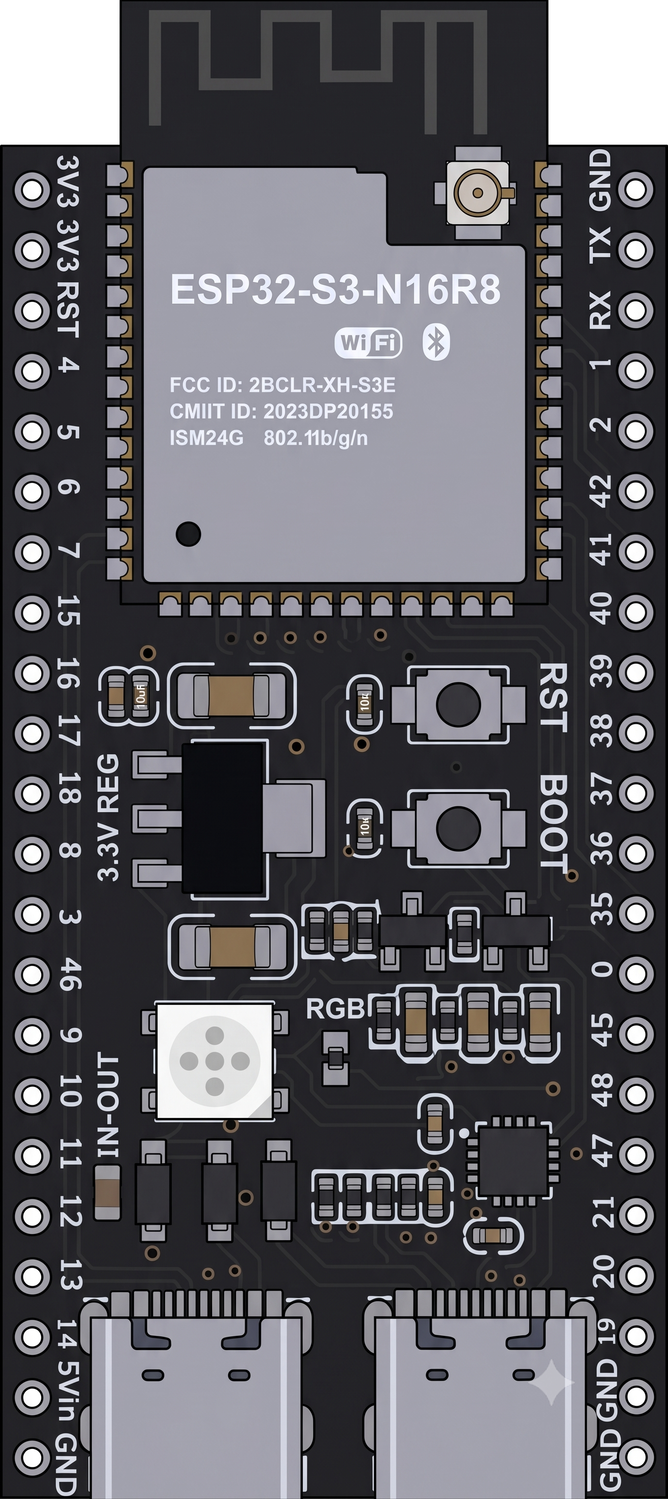
Pin Configuration and Descriptions
The ESP32-S3-N16R8 has a total of 48 pins. Below is a summary of key pins and their functions:
| Pin Number | Pin Name | Function |
|---|---|---|
| 1 | VDD | Power supply input (3.3V) |
| 2 | GND | Ground |
| 3 | GPIO0 | General-purpose I/O, boot mode selection |
| 4 | GPIO1 | General-purpose I/O, UART TX |
| 5 | GPIO2 | General-purpose I/O, UART RX |
| 6 | GPIO3 | General-purpose I/O, SPI MOSI |
| 7 | GPIO4 | General-purpose I/O, SPI MISO |
| 8 | GPIO5 | General-purpose I/O, SPI CLK |
| 9 | GPIO6 | General-purpose I/O, I2C SDA |
| 10 | GPIO7 | General-purpose I/O, I2C SCL |
| 11 | EN | Chip enable (active high) |
| 12 | ADC1_CH0 | Analog input channel 0 |
| 13 | ADC1_CH1 | Analog input channel 1 |
| ... | ... | ... (Refer to the full datasheet for all pin details) |
Usage Instructions
How to Use the ESP32-S3-N16R8 in a Circuit
- Power Supply: Connect the VDD pin to a 3.3V power source and GND to ground. Ensure the power supply is stable and capable of providing sufficient current.
- Boot Mode: To enter programming mode, connect GPIO0 to GND during reset.
- Programming: Use a USB-to-serial adapter to connect the UART pins (TX and RX) to your computer. Flash firmware using tools like esptool.py or the Arduino IDE.
- Peripherals: Connect external devices (e.g., sensors, actuators) to the GPIO pins. Configure the pins in software for the desired functionality (e.g., digital I/O, ADC, PWM).
- Wireless Communication: Configure Wi-Fi and Bluetooth settings in your firmware to enable wireless connectivity.
Important Considerations and Best Practices
- Voltage Levels: Ensure all connected peripherals operate at 3.3V logic levels to avoid damaging the ESP32-S3-N16R8.
- Decoupling Capacitors: Place decoupling capacitors (e.g., 0.1 µF) close to the VDD pin to stabilize the power supply.
- Antenna Placement: For optimal wireless performance, ensure the onboard antenna is not obstructed by metal or other conductive materials.
- Deep Sleep Mode: Use deep sleep mode to minimize power consumption in battery-powered applications.
- Firmware Updates: Regularly update the firmware to benefit from the latest features and security patches.
Example Code for Arduino UNO Integration
Below is an example of using the ESP32-S3-N16R8 with the Arduino IDE to connect to a Wi-Fi network:
#include <WiFi.h> // Include the Wi-Fi library for ESP32

// Replace with your network credentials
const char* ssid = "Your_SSID";
const char* password = "Your_PASSWORD";

void setup() {
  Serial.begin(115200); // Initialize serial communication at 115200 baud
  delay(1000); // Wait for a second to stabilize

  Serial.println("Connecting to Wi-Fi...");
  WiFi.begin(ssid, password); // Start Wi-Fi connection

  // Wait until the ESP32 connects to Wi-Fi
  while (WiFi.status() != WL_CONNECTED) {
    delay(500);
    Serial.print(".");
  }

  Serial.println("\nConnected to Wi-Fi!");
  Serial.print("IP Address: ");
  Serial.println(WiFi.localIP()); // Print the assigned IP address
}

void loop() {
  // Add your main code here
}
Troubleshooting and FAQs
Common Issues and Solutions
ESP32-S3-N16R8 Not Responding
- Cause: Incorrect power supply or wiring.
- Solution: Verify the power supply voltage (3.3V) and check all connections.
Wi-Fi Connection Fails
- Cause: Incorrect SSID or password.
- Solution: Double-check the network credentials in your code.
GPIO Pins Not Functioning
- Cause: Pins may be configured incorrectly in software.
- Solution: Ensure the pins are initialized with the correct mode (e.g., INPUT, OUTPUT).
High Power Consumption
- Cause: Device not entering deep sleep mode.
- Solution: Use the
esp_deep_sleep_start()function to enable deep sleep.
FAQs
Q: Can the ESP32-S3-N16R8 operate at 5V?
A: No, the ESP32-S3-N16R8 operates at 3.3V. Use a level shifter for 5V peripherals.Q: How do I update the firmware?
A: Use the esptool.py utility or the Arduino IDE to flash new firmware via the UART interface.Q: Can I use the ESP32-S3-N16R8 for AI/ML applications?
A: Yes, the ESP32-S3-N16R8 supports AI/ML frameworks like TensorFlow Lite Micro for edge computing tasks.
This concludes the documentation for the ESP32-S3-N16R8. For more details, refer to the official datasheet and user manual provided by Espressif Systems.