Cirkit Designer
Your all-in-one circuit design IDE
Home /
Component Documentation
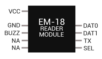
How to Use EM-18 RFID reader module: Examples, Pinouts, and Specs
Introduction
The EM-18 RFID Reader Module by Innovations is a compact radio frequency identification (RFID) reader that is capable of reading 125 kHz RFID tags and cards. It is widely used for identification and access control in various applications such as attendance systems, security systems, and personal identification.
Explore Projects Built with EM-18 RFID reader module
Biometric Access Control System with RFID and Touch Activation

This circuit is designed for security and identification purposes, featuring an RFID-RC522 module for contactless communication and a fingerprint scanner for biometric authentication. It includes an LCD display for user interaction, a touch sensor for input, a buzzer for audio feedback, and a relay module for controlling external devices. The components are interfaced with a NANO Expansion board, which likely contains a microcontroller to coordinate the operations of the system.
Arduino and ESP8266 RFID Access Control System with Servo Gate Operation
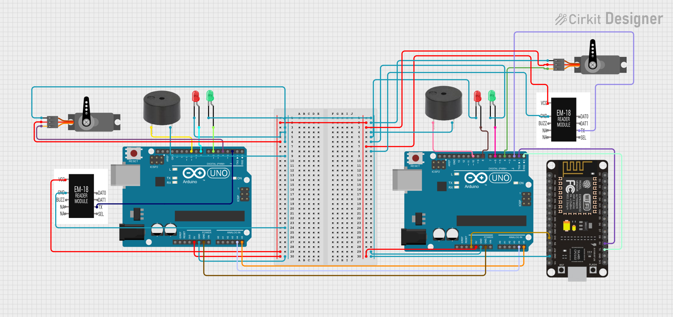
This circuit is designed for an RFID-based access control system using two Arduino UNO microcontrollers, each connected to an EM-18 RFID reader module, a servo motor, a buzzer, and two LEDs (one red and one green). The system reads RFID tags, checks for authorization, and controls gate access by actuating the servo motors. Visual (LED) and auditory (buzzer) indicators provide feedback on access granted or denied status.
Arduino and ESP8266 RFID Door Lock System with WiFi Connectivity
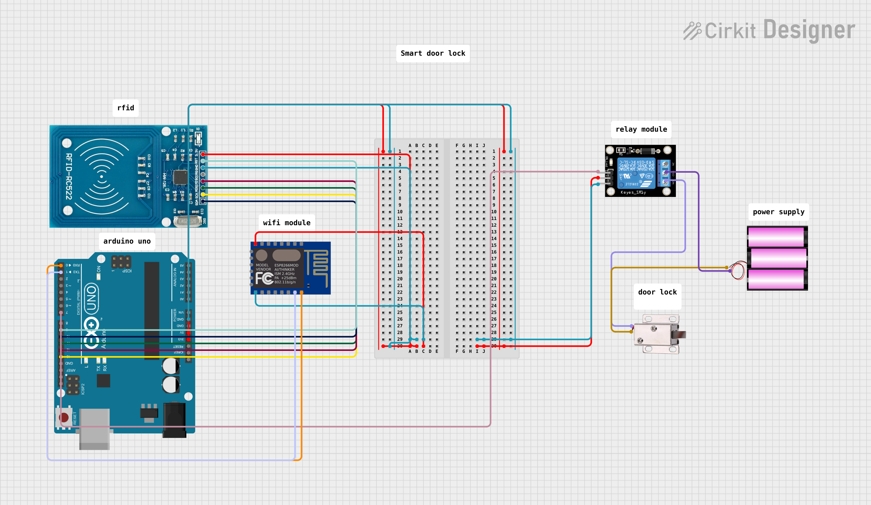
This circuit features an Arduino UNO connected to an RFID-RC522 module for RFID scanning and an ESP8266 ESP-12E WiFi module for wireless communication. The Arduino controls a KY-019 Relay module, which in turn drives a 12V solenoid lock, allowing the lock to be actuated based on RFID card detection or potentially remote commands via WiFi. The Arduino's embedded code is set up to initialize the RFID reader and output the UID of scanned cards to the serial monitor.
Arduino UNO Based RFID Access Control System with Servo Gate Operation
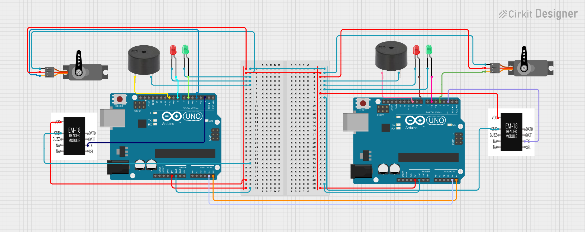
This circuit consists of two Arduino UNO microcontrollers, each connected to an EM-18 RFID reader module, a servo motor, a buzzer, and two LEDs (one red and one green). The Arduinos are programmed to read RFID tags, control access by actuating the servo motors as gates, and provide visual and auditory feedback using LEDs and buzzers. The system is designed to manage entry and exit access, likely for a secure area, by validating RFID tags against a list of authorized tags and recording entry/exit times.
Explore Projects Built with EM-18 RFID reader module
Biometric Access Control System with RFID and Touch Activation
This circuit is designed for security and identification purposes, featuring an RFID-RC522 module for contactless communication and a fingerprint scanner for biometric authentication. It includes an LCD display for user interaction, a touch sensor for input, a buzzer for audio feedback, and a relay module for controlling external devices. The components are interfaced with a NANO Expansion board, which likely contains a microcontroller to coordinate the operations of the system.
Arduino and ESP8266 RFID Access Control System with Servo Gate Operation
This circuit is designed for an RFID-based access control system using two Arduino UNO microcontrollers, each connected to an EM-18 RFID reader module, a servo motor, a buzzer, and two LEDs (one red and one green). The system reads RFID tags, checks for authorization, and controls gate access by actuating the servo motors. Visual (LED) and auditory (buzzer) indicators provide feedback on access granted or denied status.
Arduino and ESP8266 RFID Door Lock System with WiFi Connectivity
This circuit features an Arduino UNO connected to an RFID-RC522 module for RFID scanning and an ESP8266 ESP-12E WiFi module for wireless communication. The Arduino controls a KY-019 Relay module, which in turn drives a 12V solenoid lock, allowing the lock to be actuated based on RFID card detection or potentially remote commands via WiFi. The Arduino's embedded code is set up to initialize the RFID reader and output the UID of scanned cards to the serial monitor.
Arduino UNO Based RFID Access Control System with Servo Gate Operation
This circuit consists of two Arduino UNO microcontrollers, each connected to an EM-18 RFID reader module, a servo motor, a buzzer, and two LEDs (one red and one green). The Arduinos are programmed to read RFID tags, control access by actuating the servo motors as gates, and provide visual and auditory feedback using LEDs and buzzers. The system is designed to manage entry and exit access, likely for a secure area, by validating RFID tags against a list of authorized tags and recording entry/exit times.
Common Applications and Use Cases
- Access control systems
- Asset tracking
- Personal identification
- Attendance systems
- Industrial automation
Technical Specifications
Key Technical Details
- Operating Voltage: 4.5V to 5.5V
- Operating Current: 50mA (typical)
- Operating Frequency: 125 kHz
- Read Distance: Up to 10 cm (depending on the tag)
- Interface: Serial TTL
- Baud Rate: 9600 bps
Pin Configuration and Descriptions
| Pin Number | Pin Name | Description |
|---|---|---|
| 1 | VCC | Power supply (4.5V to 5.5V) |
| 2 | GND | Ground |
| 3 | TX | Serial TTL data output |
| 4 | /SEL | Enable pin (active low) |
| 5 | NC | Not connected |
Usage Instructions
How to Use the Component in a Circuit
- Connect the VCC pin to a 5V power supply.
- Connect the GND pin to the ground of the power supply.
- Connect the TX pin to the RX pin of a microcontroller like Arduino UNO.
- The /SEL pin can be connected to ground to enable the module permanently or to a digital pin of the microcontroller to control it programmatically.
Important Considerations and Best Practices
- Ensure that the power supply does not exceed 5.5V to prevent damage to the module.
- Place the RFID tags or cards close to the module for optimal reading.
- Use a proper level shifter if connecting to a microcontroller operating at a different logic level than 5V.
Example Code for Arduino UNO
#include <SoftwareSerial.h>

SoftwareSerial RFID(10, 11); // RX and TX

void setup() {
  RFID.begin(9600); // Start serial to RFID reader
  Serial.begin(9600); // Start serial to PC
}

void loop() {
  if (RFID.available() > 0) {
    // Read data from the RFID reader
    String code = RFID.readStringUntil('\n');

    // Print the RFID code to the Serial Monitor
    Serial.println(code);
  }
}
Troubleshooting and FAQs
Common Issues Users Might Face
- RFID Tag Not Detected: Ensure that the tag is within the read range and properly oriented towards the reader.
- Serial Communication Errors: Verify the baud rate and connections between the RFID module and the microcontroller.
- No Power to the Module: Check the power supply connections and voltage levels.
Solutions and Tips for Troubleshooting
- If the RFID tag is not being read, try moving it around the antenna area to find the spot with the best reception.
- Ensure that the serial connections are secure and that there is no interference from other devices.
- Use a multimeter to check the voltage levels at the VCC and GND pins to ensure they are within the specified range.
FAQs
Q: Can the EM-18 module write to RFID tags?
- A: No, the EM-18 is a read-only module and cannot write to RFID tags.
Q: What is the maximum read range of the EM-18 module?
- A: The maximum read range is up to 10 cm, but this can vary depending on the tag and environmental conditions.
Q: How do I connect multiple EM-18 modules to a single microcontroller?
- A: You can connect multiple EM-18 modules using different serial ports or by using a multiplexer for the serial lines.
Remember to always refer to the manufacturer's datasheet for the most accurate and detailed information about the EM-18 RFID Reader Module.