How to Use Submersible water level sensor 4-20mA DC24V: Examples, Pinouts, and Specs
Introduction
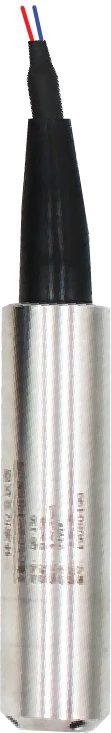
The QDY30A Submersible Water Level Sensor from QIDIAN is a robust and reliable sensor designed to measure the level of water within a given environment. Utilizing a 4-20mA current loop for signal transmission, it is capable of providing accurate readings over long distances with minimal signal loss. This sensor is commonly used in applications such as water tanks, wells, and reservoirs for water level monitoring and control systems.
Explore Projects Built with Submersible water level sensor 4-20mA DC24V
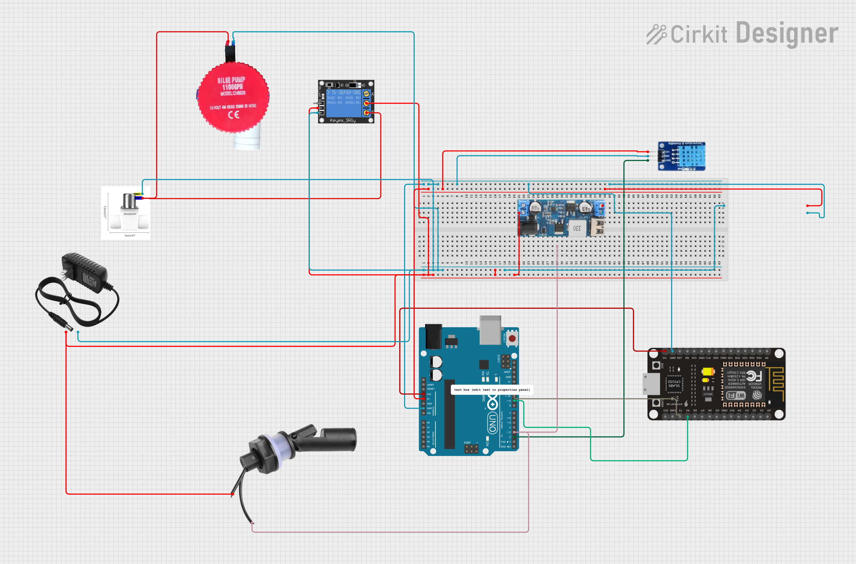
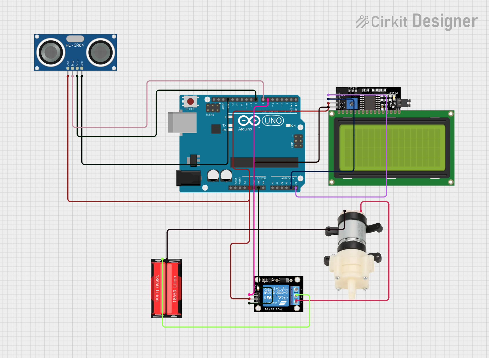
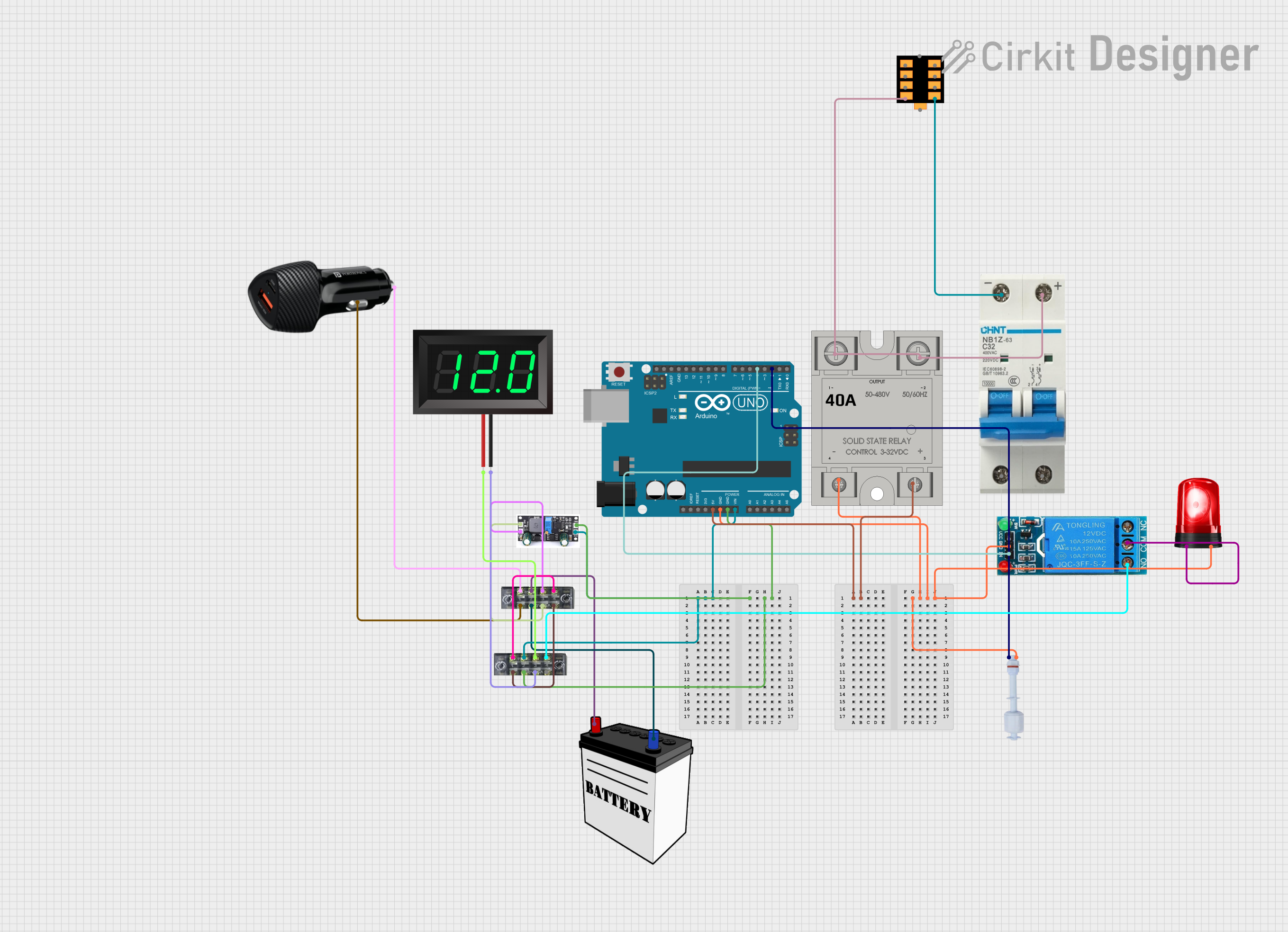
Explore Projects Built with Submersible water level sensor 4-20mA DC24V
Technical Specifications
General Specifications
- Manufacturer: QIDIAN
- Part ID: QDY30A
- Measurement Range: 0-5m, 0-10m, 0-20m, 0-30m (custom ranges available)
- Supply Voltage: DC 24V
- Output Signal: 4-20mA
- Accuracy: ±0.5% FS (Full Scale)
- Operating Temperature: -20°C to 85°C
- Protection Grade: IP68
- Material: Stainless steel housing
Electrical Connections
| Pin Number | Description | Notes |
|---|---|---|
| 1 | Power Supply (+) | Connect to DC 24V |
| 2 | Current Output | 4-20mA signal |
| 3 | Power Supply (-) | Ground connection |
Usage Instructions
Integration into a Circuit
Power Supply: Ensure that the sensor is connected to a stable DC 24V power supply. The positive terminal should be connected to pin 1, and the negative terminal to pin 3.
Signal Reading: Connect pin 2 to a current loop receiver, such as a PLC (Programmable Logic Controller) or an analog input module capable of reading 4-20mA signals.
Mounting: Securely mount the sensor in the desired location, ensuring that it is fully submerged for accurate readings.
Best Practices
- Calibration: Prior to deployment, calibrate the sensor according to the manufacturer's instructions to ensure accuracy.
- Cable Protection: Use appropriate cable glands or conduit to protect the sensor's cable when routing it, especially in harsh environments.
- Electrical Noise: Avoid running sensor cables alongside high-voltage or high-current power lines to prevent electromagnetic interference.
Example Arduino Connection
To connect the QDY30A sensor to an Arduino UNO, you will need an external 4-20mA to 0-5V converter module, as the Arduino cannot directly read 4-20mA signals.
// Example code to read the water level from a QDY30A sensor using an Arduino UNO

#include <Wire.h>

const int analogInPin = A0; // Analog input pin connected to the converter output

void setup() {
  Serial.begin(9600); // Initialize serial communication at 9600 bps
}

void loop() {
  int sensorValue = analogRead(analogInPin); // Read the analog value
  float voltage = sensorValue * (5.0 / 1023.0); // Convert to voltage
  float current = (voltage / 5.0) * 20.0; // Convert voltage to current (4-20mA)

  // Assuming a linear relationship for demonstration purposes
  // Replace with actual calibration values for accurate measurement
  float waterLevel = (current - 4) * (30.0 / 16.0); // Convert current to water level

  Serial.print("Current: ");
  Serial.print(current);
  Serial.print("mA, Water Level: ");
  Serial.print(waterLevel);
  Serial.println("m");

  delay(1000); // Wait for a second before the next read
}
Troubleshooting and FAQs
Common Issues
- Inaccurate Readings: Ensure the sensor is properly calibrated and that there is no electrical interference affecting the signal.
- No Output Signal: Check the power supply and connections to ensure the sensor is powered and correctly wired.
- Sensor Not Responding: Verify that the sensor is not damaged and that the environmental conditions are within the specified operating range.
FAQs
Q: Can the sensor be used in saltwater? A: Yes, the stainless steel housing is designed to withstand harsh environments, including saltwater.
Q: What is the maximum cable length for the sensor? A: The 4-20mA current loop allows for long cable runs without significant signal degradation. However, consult the manufacturer's documentation for specific recommendations.
Q: How do I calibrate the sensor? A: Calibration procedures are provided by the manufacturer. It typically involves submerging the sensor to known depths and adjusting the output signal to match the actual water level.
For further assistance, please contact QIDIAN's technical support.