
How to Use MCB 1 Phase: Examples, Pinouts, and Specs
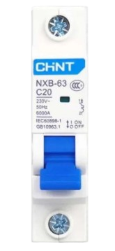
 Design with MCB 1 Phase in Cirkit Designer
Introduction
The MCB 1 Phase (Miniature Circuit Breaker) is an essential safety device designed for single-phase electrical circuits. It provides overcurrent protection by automatically disconnecting the circuit when excessive current flows, preventing damage to electrical devices and reducing the risk of fire or electrical hazards. MCBs are widely used in residential, commercial, and industrial applications to ensure the safety and reliability of electrical systems.
Explore Projects Built with MCB 1 Phase
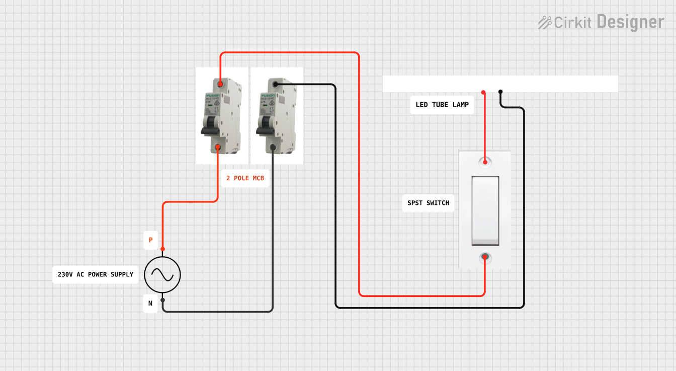 Open Project in Cirkit Designer
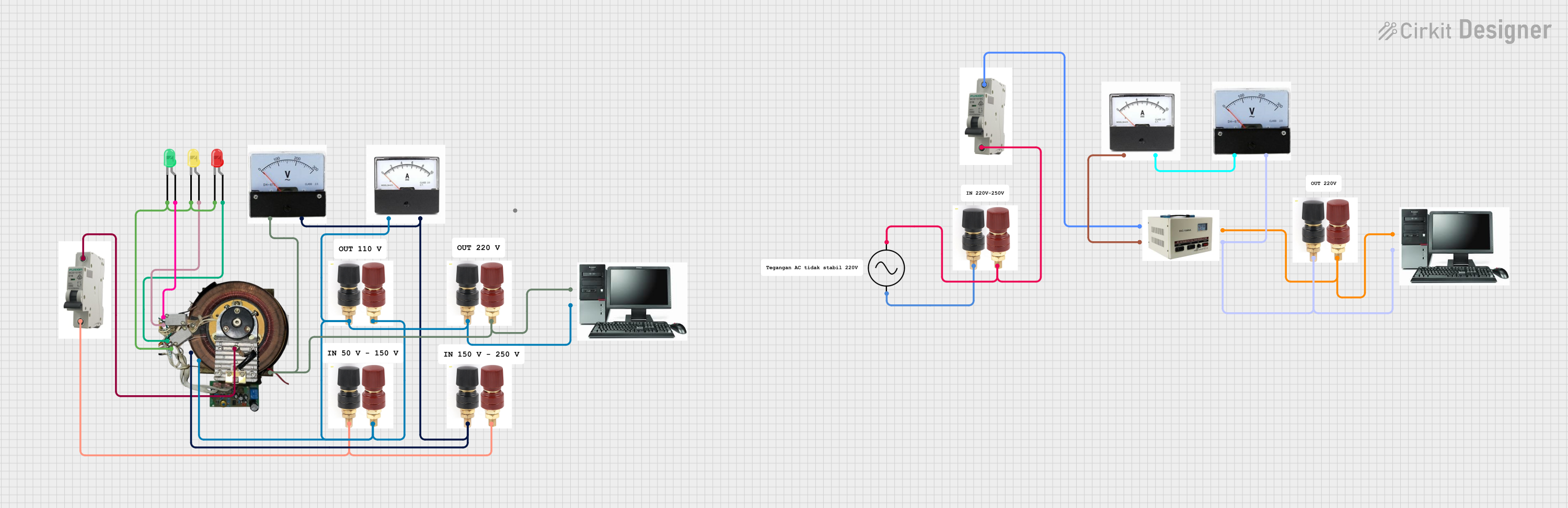 Open Project in Cirkit Designer
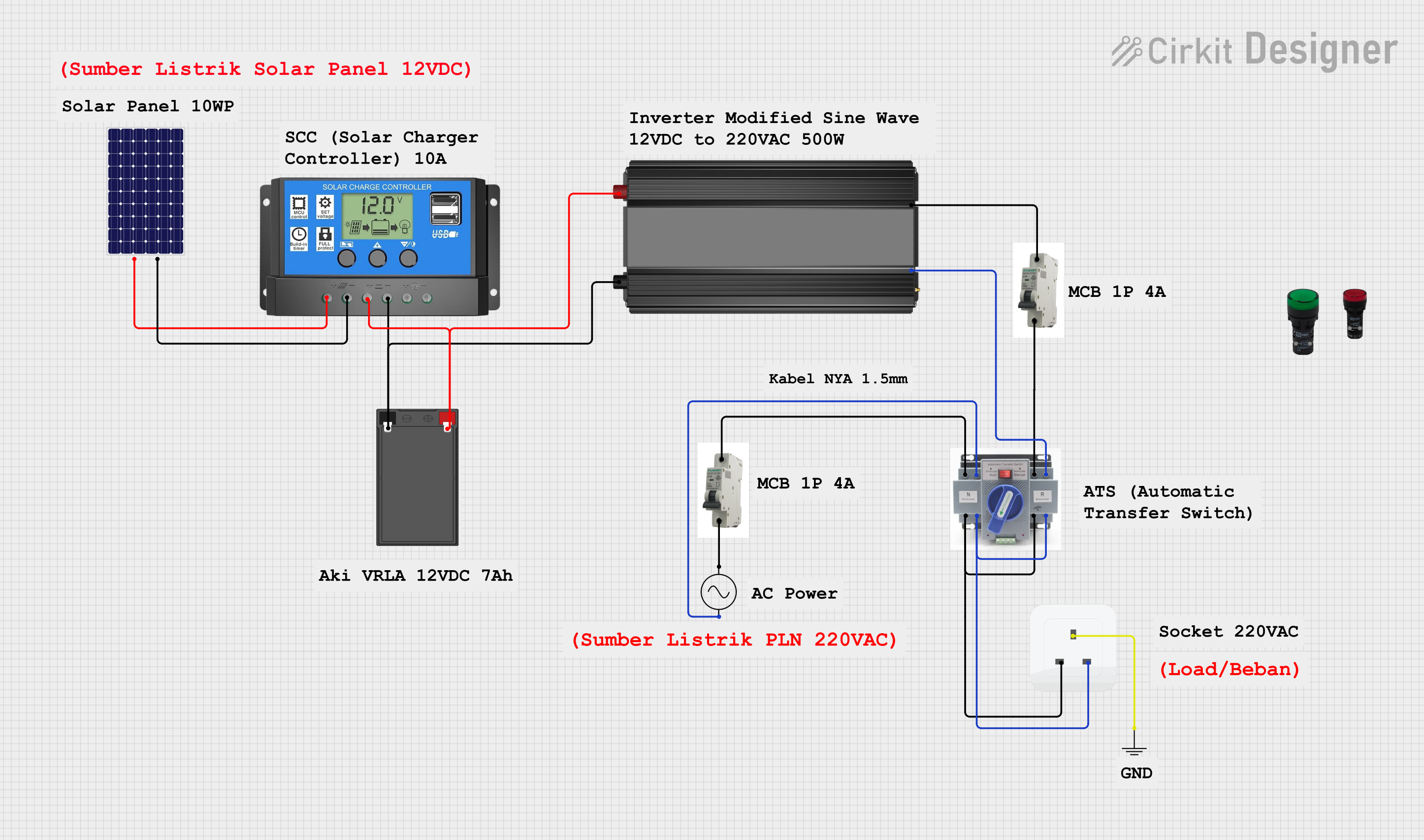 Open Project in Cirkit Designer
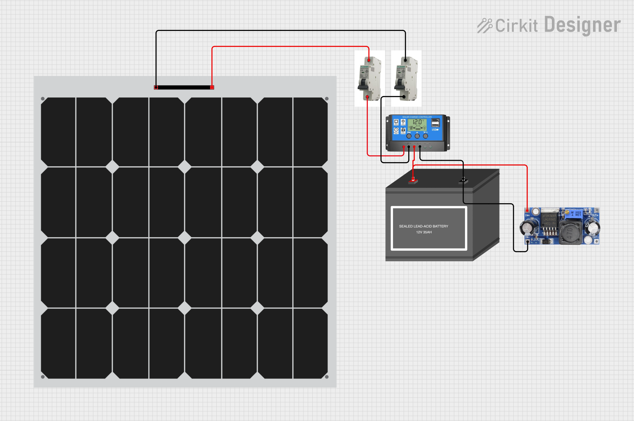 Open Project in Cirkit Designer
Explore Projects Built with MCB 1 Phase
Open Project in Cirkit DesignerOpen Project in Cirkit DesignerOpen Project in Cirkit DesignerOpen Project in Cirkit DesignerCommon Applications and Use Cases
- Protection of household electrical circuits (e.g., lighting, outlets, appliances)
- Safeguarding industrial equipment from overcurrent or short circuits
- Use in distribution boards for single-phase systems
- Overload and short-circuit protection in small-scale commercial setups
Technical Specifications
The following table outlines the key technical details of the MCB 1 Phase:
| Parameter | Specification |
|---|---|
| Rated Voltage | 230V AC |
| Rated Current | 6A, 10A, 16A, 20A, 32A (varies by model) |
| Breaking Capacity | 6kA |
| Number of Poles | 1 (Single Phase) |
| Tripping Curve | B, C, or D (depending on application) |
| Frequency | 50/60 Hz |
| Operating Temperature | -5°C to +55°C |
| Mounting Type | DIN Rail (35mm standard) |
| Compliance Standards | IEC 60898-1 |
Pin Configuration and Descriptions
The MCB 1 Phase does not have traditional pins but instead features terminal connections for input and output wiring. The table below describes these terminals:
| Terminal | Description |
|---|---|
| Line (Input) | Connects to the live wire from the power source |
| Load (Output) | Connects to the live wire of the protected circuit |
| Neutral | Not applicable (neutral wire bypasses the MCB) |
Usage Instructions
How to Use the MCB 1 Phase in a Circuit
- Mounting the MCB: Secure the MCB onto a standard 35mm DIN rail in the distribution board.
- Wiring:
- Connect the live wire from the power source to the Line (Input) terminal.
- Connect the live wire of the circuit to be protected to the Load (Output) terminal.
- Ensure the neutral wire bypasses the MCB and connects directly to the neutral bus bar.
- Power On: Switch the MCB to the "ON" position to energize the circuit.
- Testing: Use the test button (if available) to verify the MCB's functionality.
Important Considerations and Best Practices
- Select the Correct Rating: Choose an MCB with a current rating and tripping curve suitable for your application to avoid nuisance tripping or insufficient protection.
- Tighten Connections: Ensure all terminal screws are securely tightened to prevent loose connections, which can cause overheating.
- Avoid Overloading: Do not exceed the rated current of the MCB, as this may lead to frequent tripping or damage.
- Periodic Testing: Regularly test the MCB using the test button (if available) to ensure it is functioning correctly.
- Use in Dry Environments: Install the MCB in a dry, well-ventilated area to prevent moisture-related issues.
Arduino Integration
While MCBs are not directly connected to microcontrollers like Arduino, they can be used in circuits that power Arduino-based systems. For example, an MCB can protect the power supply feeding an Arduino project from overcurrent or short circuits.
Troubleshooting and FAQs
Common Issues and Solutions
| Issue | Possible Cause | Solution |
|---|---|---|
| MCB trips frequently | Overloaded circuit or short circuit | Reduce the load or check for wiring faults |
| MCB does not trip during a fault | Faulty MCB or incorrect rating | Replace the MCB or select the correct rating |
| Loose connections at terminals | Improper tightening of terminal screws | Re-tighten the screws securely |
| MCB feels warm during operation | High current flow or poor ventilation | Ensure proper ventilation and check the load |
FAQs
Can I use an MCB 1 Phase for a three-phase system?
- No, the MCB 1 Phase is designed specifically for single-phase circuits. For three-phase systems, use a three-phase MCB.
What is the difference between B, C, and D tripping curves?
- B Curve: Trips at 3-5 times the rated current, suitable for residential use.
- C Curve: Trips at 5-10 times the rated current, ideal for commercial and industrial applications.
- D Curve: Trips at 10-20 times the rated current, used for heavy-duty equipment with high inrush currents.
How do I know if my MCB is faulty?
- If the MCB does not trip during a fault or trips without any apparent reason, it may be faulty. Test it using the test button or consult a professional electrician.
Can I reset the MCB after it trips?
- Yes, switch the MCB to the "OFF" position, identify and resolve the cause of the trip, and then switch it back to the "ON" position.
By following this documentation, you can safely and effectively use the MCB 1 Phase in your electrical systems.