How to Use nrf2401 2.4Gz: Examples, Pinouts, and Specs
Introduction
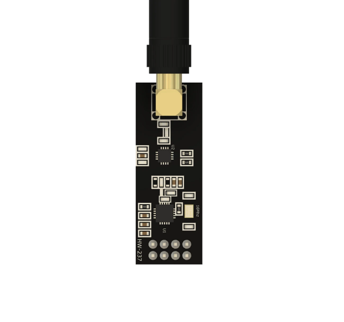
The nRF2401 is a low-power, 2.4 GHz transceiver designed for wireless communication in short-range applications. Manufactured by Arduino, this component is ideal for creating wireless links in IoT devices, remote controls, wireless sensors, and other embedded systems. Its compact design and low power consumption make it a popular choice for battery-powered devices.
Explore Projects Built with nrf2401 2.4Gz
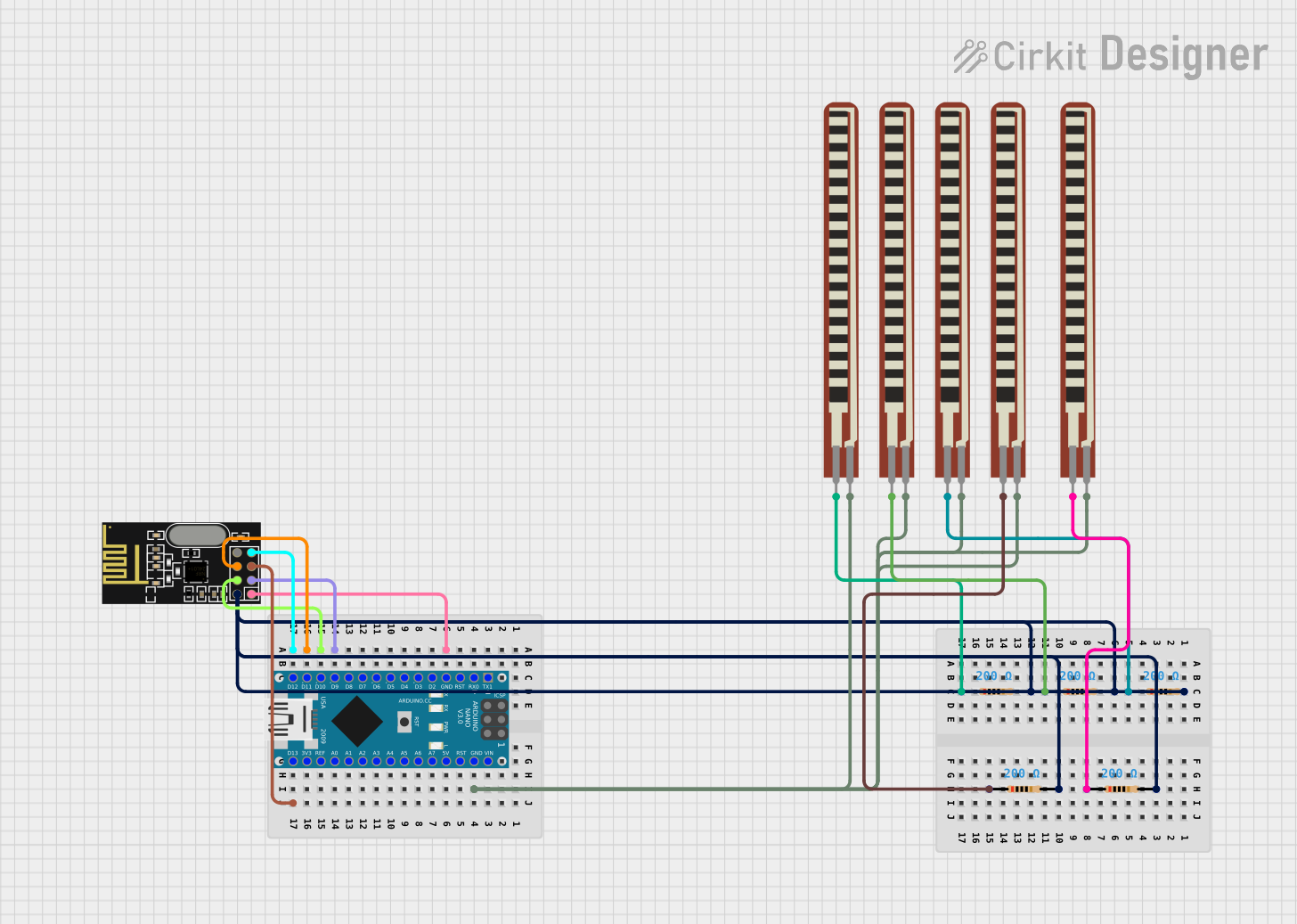
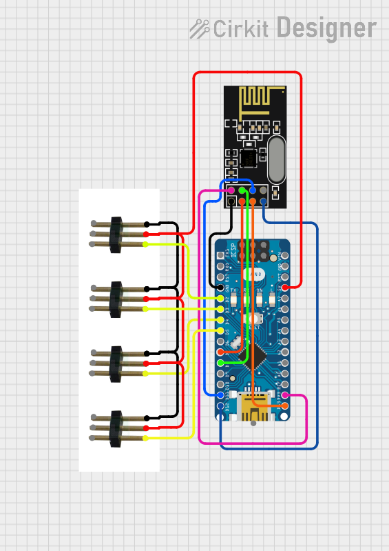
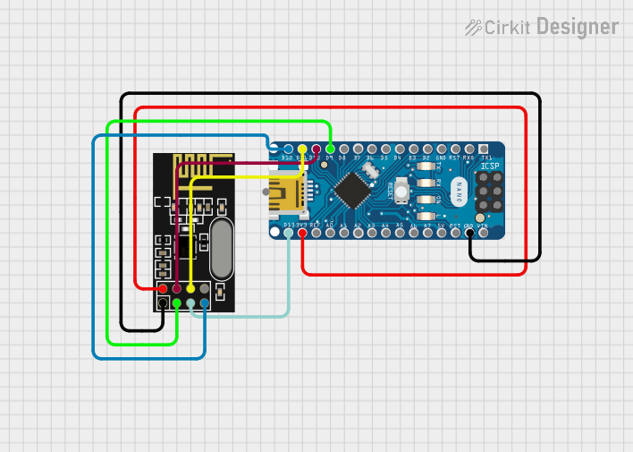

Explore Projects Built with nrf2401 2.4Gz
Common Applications
- Wireless remote controls
- IoT (Internet of Things) devices
- Wireless sensors and data acquisition systems
- Home automation systems
- Wireless gaming peripherals
Technical Specifications
The nRF2401 transceiver is designed to operate in the 2.4 GHz ISM band and supports multiple data rates and modulation schemes. Below are its key technical details:
Key Specifications
| Parameter | Value |
|---|---|
| Operating Frequency | 2.4 GHz ISM Band |
| Modulation Scheme | GFSK (Gaussian Frequency Shift Keying) |
| Data Rate | 250 kbps, 1 Mbps, 2 Mbps |
| Operating Voltage | 1.9V to 3.6V |
| Current Consumption | 10.5 mA (TX at 0 dBm) |
| Standby Current | 22 µA |
| Communication Interface | SPI (Serial Peripheral Interface) |
| Maximum Output Power | 0 dBm |
| Sensitivity | -90 dBm at 1 Mbps |
| Range | Up to 100 meters (line of sight) |
Pin Configuration and Descriptions
The nRF2401 module typically comes with 8 pins. Below is the pinout and description:
| Pin Number | Pin Name | Description |
|---|---|---|
| 1 | GND | Ground connection |
| 2 | VCC | Power supply (1.9V to 3.6V) |
| 3 | CE | Chip Enable: Activates the transceiver for transmission or reception |
| 4 | CSN | Chip Select Not: Enables SPI communication when pulled low |
| 5 | SCK | Serial Clock: SPI clock input |
| 6 | MOSI | Master Out Slave In: SPI data input |
| 7 | MISO | Master In Slave Out: SPI data output |
| 8 | IRQ | Interrupt Request: Indicates data received or transmission complete |
Usage Instructions
The nRF2401 transceiver is commonly used with microcontrollers like the Arduino UNO. Below are the steps to use the module in a circuit:
Circuit Connection
- Power Supply: Connect the
VCCpin to a 3.3V power source (do not use 5V as it may damage the module). Connect theGNDpin to the ground. - SPI Interface: Connect the
CSN,SCK,MOSI, andMISOpins to the corresponding SPI pins on the Arduino UNO:CSN→ Pin 10 (default SPI chip select)SCK→ Pin 13MOSI→ Pin 11MISO→ Pin 12
- Control Pins: Connect the
CEpin to any available digital pin on the Arduino (e.g., Pin 9). TheIRQpin can be left unconnected if interrupts are not used.
Arduino Code Example
Below is an example of how to use the nRF2401 module with an Arduino UNO to send and receive data. This example uses the popular RF24 library.
#include <SPI.h>
#include <nRF24L01.h>
#include <RF24.h>

// Define the CE and CSN pins for the nRF2401 module
#define CE_PIN 9
#define CSN_PIN 10

// Create an RF24 object
RF24 radio(CE_PIN, CSN_PIN);

// Define the address for communication
const byte address[6] = "00001";

void setup() {
  Serial.begin(9600); // Initialize serial communication
  radio.begin();      // Initialize the nRF2401 module
  radio.openWritingPipe(address); // Set the address for transmission
  radio.setPALevel(RF24_PA_LOW);  // Set power level to low
  radio.stopListening();          // Set the module to transmit mode
}

void loop() {
  const char text[] = "Hello, World!"; // Data to send
  bool success = radio.write(&text, sizeof(text)); // Send data

  if (success) {
    Serial.println("Data sent successfully!");
  } else {
    Serial.println("Data transmission failed.");
  }

  delay(1000); // Wait 1 second before sending again
}
Important Considerations
- Power Supply: The nRF2401 operates at 3.3V. If using a 5V microcontroller, use a voltage regulator or level shifter to avoid damage.
- Antenna Placement: Ensure the module's antenna is not obstructed by metal objects to maximize range.
- Decoupling Capacitor: Place a 10 µF capacitor between
VCCandGNDto stabilize the power supply.
Troubleshooting and FAQs
Common Issues
No Communication Between Modules
- Ensure both modules are configured with the same address and data rate.
- Verify the wiring and SPI connections.
- Check the power supply voltage (must be 3.3V).
Short Range or Unstable Connection
- Ensure the antenna is properly positioned and not obstructed.
- Use a lower data rate (e.g., 250 kbps) to improve range and reliability.
Module Not Responding
- Verify that the
CEandCSNpins are correctly connected to the microcontroller. - Check for loose or incorrect wiring.
- Verify that the
FAQs
Q: Can the nRF2401 work with a 5V microcontroller?
A: Yes, but you must use a 3.3V regulator or level shifter for the VCC and SPI pins to avoid damaging the module.
Q: What is the maximum range of the nRF2401?
A: The module can achieve up to 100 meters in line-of-sight conditions. Obstacles and interference may reduce the range.
Q: Can I use multiple nRF2401 modules in the same area?
A: Yes, the module supports multiple channels and addresses, allowing multiple devices to communicate without interference.
Q: How do I increase the range of the module?
A: Use a lower data rate (e.g., 250 kbps) and ensure the antenna is unobstructed for better range.
By following this documentation, you can effectively integrate the nRF2401 transceiver into your projects for reliable wireless communication.