How to Use OV2640 18 PIN Board: Examples, Pinouts, and Specs
Introduction
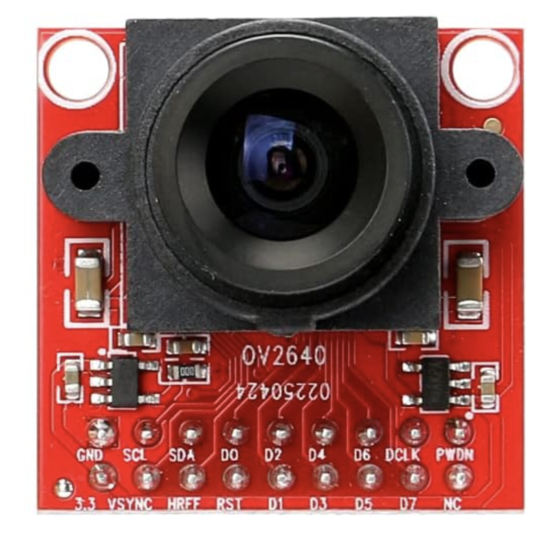
The OV2640 18 PIN Board by STMicroelectronics is a compact camera module featuring the OV2640 image sensor. This module is capable of capturing high-resolution images and video, making it ideal for applications requiring visual data acquisition. Its 18-pin interface ensures seamless integration with microcontrollers and development boards, including popular platforms like Arduino and ESP32.
Explore Projects Built with OV2640 18 PIN Board


Explore Projects Built with OV2640 18 PIN Board
Common Applications and Use Cases
- Surveillance Systems: Used in security cameras for real-time monitoring.
- IoT Devices: Enables image and video capture in smart devices.
- Robotics: Provides vision capabilities for autonomous robots.
- Machine Learning: Used in image recognition and object detection projects.
- DIY Projects: Ideal for hobbyists building camera-based systems.
Technical Specifications
The following table outlines the key technical details of the OV2640 18 PIN Board:
| Parameter | Specification |
|---|---|
| Image Sensor | OV2640 |
| Resolution | Up to 2 Megapixels (1600 x 1200) |
| Pixel Size | 2.2 µm x 2.2 µm |
| Lens | Integrated lens with a 60° field of view |
| Interface | 18-pin connector |
| Supply Voltage | 3.3V (typical) |
| Power Consumption | 120 mW (active mode) |
| Output Format | YUV, RGB, JPEG |
| Operating Temperature | -30°C to 70°C |
| Dimensions | 24mm x 24mm |
Pin Configuration and Descriptions
The OV2640 18 PIN Board features an 18-pin interface. The pinout is as follows:
| Pin Number | Pin Name | Description |
|---|---|---|
| 1 | GND | Ground |
| 2 | VCC | Power supply (3.3V) |
| 3 | SCL | I2C Clock |
| 4 | SDA | I2C Data |
| 5 | VSYNC | Vertical synchronization signal |
| 6 | HREF | Horizontal reference signal |
| 7 | PCLK | Pixel clock |
| 8 | XCLK | External clock input |
| 9 | D0 | Data bit 0 |
| 10 | D1 | Data bit 1 |
| 11 | D2 | Data bit 2 |
| 12 | D3 | Data bit 3 |
| 13 | D4 | Data bit 4 |
| 14 | D5 | Data bit 5 |
| 15 | D6 | Data bit 6 |
| 16 | D7 | Data bit 7 |
| 17 | RESET | Reset signal (active low) |
| 18 | PWDN | Power down mode (active high) |
Usage Instructions
How to Use the OV2640 18 PIN Board in a Circuit
- Power Supply: Connect the VCC pin to a 3.3V power source and the GND pin to ground.
- Clock Signal: Provide an external clock signal (XCLK) to the module. A typical frequency is 24 MHz.
- I2C Communication: Use the SCL and SDA pins to configure the module via I2C. The default I2C address is
0x30. - Data Output: Connect the data pins (D0-D7) to the microcontroller for image data transfer.
- Synchronization: Use the VSYNC, HREF, and PCLK pins for proper timing and synchronization of image data.
Important Considerations and Best Practices
- Voltage Levels: Ensure all signal lines are 3.3V logic compatible. Use level shifters if interfacing with 5V systems.
- Clock Stability: Provide a stable and accurate clock signal to the XCLK pin for optimal performance.
- Lens Adjustment: If the module includes a focus-adjustable lens, fine-tune it for your application.
- Heat Management: Avoid prolonged operation in high-temperature environments to prevent overheating.
Example: Connecting to an Arduino UNO
The OV2640 18 PIN Board can be connected to an Arduino UNO using the following wiring:
| OV2640 Pin | Arduino Pin |
|---|---|
| VCC | 3.3V |
| GND | GND |
| SCL | A5 (I2C Clock) |
| SDA | A4 (I2C Data) |
| RESET | Digital Pin 7 |
| PWDN | Digital Pin 8 |
Below is an example Arduino sketch to initialize the OV2640 module:
#include <Wire.h>

// OV2640 I2C address
#define OV2640_I2C_ADDR 0x30

// Pin definitions
#define RESET_PIN 7
#define PWDN_PIN 8

void setup() {
  // Initialize serial communication for debugging
  Serial.begin(9600);

  // Initialize I2C communication
  Wire.begin();

  // Configure RESET and PWDN pins
  pinMode(RESET_PIN, OUTPUT);
  pinMode(PWDN_PIN, OUTPUT);

  // Reset the camera module
  digitalWrite(RESET_PIN, LOW);
  delay(10);
  digitalWrite(RESET_PIN, HIGH);
  delay(10);

  // Wake up the camera module
  digitalWrite(PWDN_PIN, LOW);
  delay(10);

  // Test I2C communication
  Wire.beginTransmission(OV2640_I2C_ADDR);
  if (Wire.endTransmission() == 0) {
    Serial.println("OV2640 detected successfully!");
  } else {
    Serial.println("Failed to detect OV2640.");
  }
}

void loop() {
  // Add your image capture or processing code here
}
Troubleshooting and FAQs
Common Issues and Solutions
Module Not Detected via I2C
- Cause: Incorrect wiring or I2C address.
- Solution: Double-check the connections and ensure the I2C address is set to
0x30.
No Image Output
- Cause: Missing or unstable clock signal on the XCLK pin.
- Solution: Verify the clock source and ensure it provides a stable 24 MHz signal.
Distorted or Blurry Images
- Cause: Incorrect lens focus or insufficient lighting.
- Solution: Adjust the lens focus and ensure adequate lighting for the scene.
Overheating
- Cause: Prolonged operation in high-temperature environments.
- Solution: Improve ventilation or reduce the operating time.
FAQs
Q: Can the OV2640 capture video?
- A: Yes, the module supports video capture in various resolutions, including VGA and QVGA.
Q: Is the OV2640 compatible with 5V systems?
- A: No, the module operates at 3.3V. Use level shifters for 5V systems.
Q: What is the maximum resolution supported?
- A: The OV2640 supports up to 2 Megapixels (1600 x 1200).
Q: Can I use this module with an ESP32?
- A: Yes, the OV2640 is commonly used with ESP32 boards for camera-based projects.