Cirkit Designer Logo
Cirkit Designer
Your all-in-one circuit design IDE
Home / 
Component Documentation

How to Use ESP32-CAM MB FLIP: Examples, Pinouts, and Specs

Image of ESP32-CAM MB FLIP
Cirkit Designer LogoDesign with ESP32-CAM MB FLIP in Cirkit Designer

Introduction

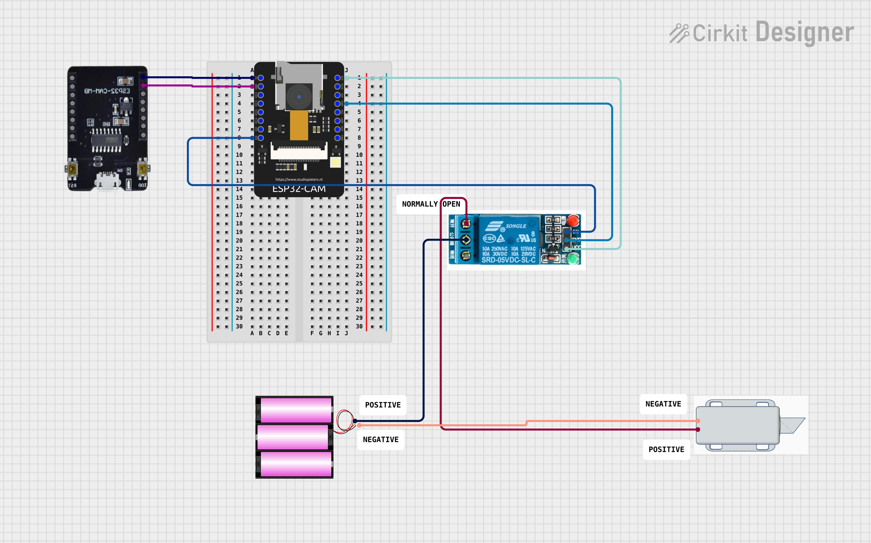
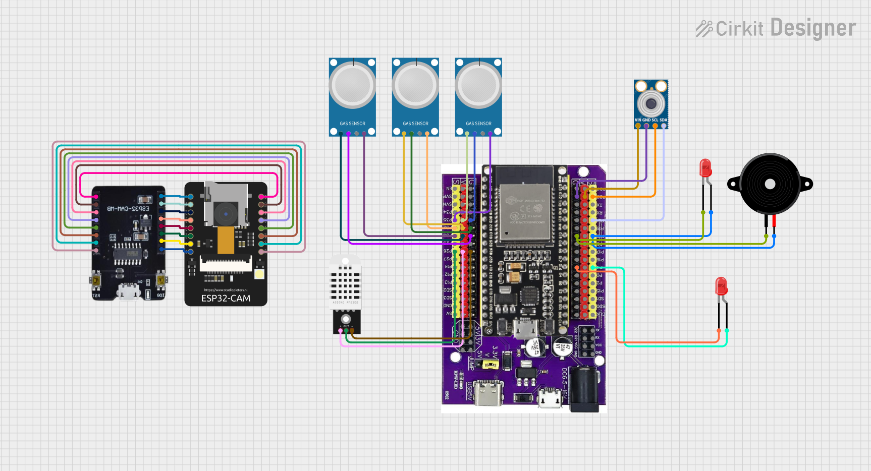
The ESP32-CAM MB FLIP is a versatile development board that combines the powerful ESP32 microcontroller with an integrated camera module. This board is ideal for applications such as home automation, surveillance systems, remote monitoring, and IoT projects where image or video capture is required alongside wireless connectivity.

Explore Projects Built with ESP32-CAM MB FLIP

Use Cirkit Designer to design, explore, and prototype these projects online. Some projects support real-time simulation. Click "Open Project" to start designing instantly!
ESP32-CAM Controlled Wi-Fi Smart Lock
Image of ESP32: A project utilizing ESP32-CAM MB FLIP in a practical application
This circuit features an ESP32-CAM microcontroller configured to connect to a WiFi network and potentially perform facial recognition or other camera-related tasks. It controls a 5V relay, which in turn controls a 12V solenoid lock, allowing the lock to be engaged or disengaged based on the microcontroller's logic. The ESP32-CAM is powered by 5V, and the relay is used to switch the 12V power from the battery to the solenoid lock.
Cirkit Designer LogoOpen Project in Cirkit Designer
ESP32 CAM Wi-Fi Controlled Camera with FTDI Programmer
Image of R: A project utilizing ESP32-CAM MB FLIP in a practical application
This circuit consists of an ESP32 CAM module connected to an FTDI Programmer for power and serial communication. The ESP32 CAM is programmed to capture images and stream them over WiFi, acting as a web server to provide live video feed.
Cirkit Designer LogoOpen Project in Cirkit Designer
ESP32-CAM Based Environmental Monitoring System with Gas Detection and Infrared Temperature Sensing
Image of Pyrosentrix: A project utilizing ESP32-CAM MB FLIP in a practical application
This is a multi-sensor environmental monitoring system with image capturing capabilities. It uses an ESP32 microcontroller to interface with gas, temperature, and humidity sensors, as well as an infrared temperature sensor and an ESP32-CAM module. The system can provide visual and audio alerts through connected LEDs and a piezo speaker.
Cirkit Designer LogoOpen Project in Cirkit Designer
ESP32 CAM Wi-Fi Controlled Camera with FTDI Programmer
Image of ESP32 CAM: A project utilizing ESP32-CAM MB FLIP in a practical application
This circuit consists of an ESP32 CAM module connected to an FTDI Programmer for power and serial communication. The ESP32 CAM is programmed to capture images and stream them over WiFi, acting as a web server to provide a live video feed.
Cirkit Designer LogoOpen Project in Cirkit Designer

Explore Projects Built with ESP32-CAM MB FLIP

Use Cirkit Designer to design, explore, and prototype these projects online. Some projects support real-time simulation. Click "Open Project" to start designing instantly!
Image of ESP32: A project utilizing ESP32-CAM MB FLIP in a practical application
ESP32-CAM Controlled Wi-Fi Smart Lock
This circuit features an ESP32-CAM microcontroller configured to connect to a WiFi network and potentially perform facial recognition or other camera-related tasks. It controls a 5V relay, which in turn controls a 12V solenoid lock, allowing the lock to be engaged or disengaged based on the microcontroller's logic. The ESP32-CAM is powered by 5V, and the relay is used to switch the 12V power from the battery to the solenoid lock.
Cirkit Designer LogoOpen Project in Cirkit Designer
Image of R: A project utilizing ESP32-CAM MB FLIP in a practical application
ESP32 CAM Wi-Fi Controlled Camera with FTDI Programmer
This circuit consists of an ESP32 CAM module connected to an FTDI Programmer for power and serial communication. The ESP32 CAM is programmed to capture images and stream them over WiFi, acting as a web server to provide live video feed.
Cirkit Designer LogoOpen Project in Cirkit Designer
Image of Pyrosentrix: A project utilizing ESP32-CAM MB FLIP in a practical application
ESP32-CAM Based Environmental Monitoring System with Gas Detection and Infrared Temperature Sensing
This is a multi-sensor environmental monitoring system with image capturing capabilities. It uses an ESP32 microcontroller to interface with gas, temperature, and humidity sensors, as well as an infrared temperature sensor and an ESP32-CAM module. The system can provide visual and audio alerts through connected LEDs and a piezo speaker.
Cirkit Designer LogoOpen Project in Cirkit Designer
Image of ESP32 CAM: A project utilizing ESP32-CAM MB FLIP in a practical application
ESP32 CAM Wi-Fi Controlled Camera with FTDI Programmer
This circuit consists of an ESP32 CAM module connected to an FTDI Programmer for power and serial communication. The ESP32 CAM is programmed to capture images and stream them over WiFi, acting as a web server to provide a live video feed.
Cirkit Designer LogoOpen Project in Cirkit Designer

Common Applications and Use Cases

  • Home security cameras
  • QR code readers
  • Face recognition systems
  • Remote wildlife monitoring
  • Industrial automation and inspection

Technical Specifications

Key Technical Details

  • Microcontroller: ESP32-D0WDQ6 (dual-core, up to 160 MHz)
  • RAM: 520 KB SRAM
  • Flash Memory: 4 MB
  • Wi-Fi: 802.11 b/g/n
  • Bluetooth: v4.2 BR/EDR and BLE standards
  • Camera Interface: Supports OV2640 and OV7670 cameras
  • I/O Pins: GPIO, UART, SPI, I2C, PWM
  • Operating Voltage: 5V (via USB) or 3.3V (via pin headers)
  • Current Consumption: ~80 mA during operation

Pin Configuration and Descriptions

Pin Number Function Description
1 GND Ground
2 3V3 3.3V power supply
3 U0T UART0 Transmit
4 U0R UART0 Receive
5 GPIO 3 General Purpose Input/Output
6 GPIO 1 General Purpose Input/Output
7 GPIO 0 BOOT button when pulled to GND
8 GPIO 2 Onboard LED, also used for camera data bit 0
... ... ...
n GND Ground

Note: This is a partial list. Refer to the ESP32-CAM MB FLIP datasheet for the full pinout.

Usage Instructions

How to Use the Component in a Circuit

  1. Powering the Board:

    • Ensure that the board is powered through the 5V pin or via the micro USB port.
    • Do not exceed the recommended voltage to prevent damage.
  2. Connecting the Camera:

    • Attach the camera module to the ESP32-CAM MB FLIP using the provided connector.
    • Ensure that the camera is properly aligned and secured.
  3. Programming the Board:

    • Use the Arduino IDE or ESP-IDF for programming the ESP32-CAM.
    • Select the correct board and port before uploading the code.
  4. Accessing the Camera:

    • Implement camera initialization code in your firmware.
    • Use the provided libraries to capture images or video streams.

Important Considerations and Best Practices

  • Antenna Selection: Ensure that the onboard antenna or an external antenna is properly connected for optimal Wi-Fi performance.
  • Power Supply: Use a stable power source capable of delivering sufficient current, especially when using Wi-Fi or capturing images.
  • Heat Dissipation: Provide adequate cooling if the board is used in high-performance or continuous operation modes.

Troubleshooting and FAQs

Common Issues Users Might Face

  • Camera Not Detected:

    • Check the camera connection and ensure it is properly seated.
    • Verify that the camera model is supported by the ESP32-CAM MB FLIP.
  • Wi-Fi Connectivity Problems:

    • Ensure the antenna is properly connected.
    • Check the Wi-Fi credentials and settings in your code.
  • Board Not Responding:

    • Verify the power supply and ensure the board is not underpowered.
    • Check for any shorts or incorrect wiring in your setup.

Solutions and Tips for Troubleshooting

  • Reset the Board: Use the onboard RESET button to restart the board if it becomes unresponsive.
  • Firmware Update: Ensure that the latest firmware is installed and that the board is properly flashed.
  • Serial Output: Use the serial monitor to debug and check for error messages during boot or operation.

Example Code for Arduino UNO

#include "esp_camera.h"

// Replace with your network credentials
const char* ssid = "YOUR_SSID";
const char* password = "YOUR_PASSWORD";

void setup() {
  Serial.begin(115200);
  // Camera configuration and initialization
  camera_config_t config;
  config.ledc_channel = LEDC_CHANNEL_0;
  config.ledc_timer = LEDC_TIMER_0;
  config.pin_d0 = Y2_GPIO_NUM;
  // ... additional camera configuration settings
  esp_err_t err = esp_camera_init(&config);
  if (err != ESP_OK) {
    Serial.printf("Camera init failed with error 0x%x", err);
    return;
  }

  // Connect to Wi-Fi
  WiFi.begin(ssid, password);
  while (WiFi.status() != WL_CONNECTED) {
    delay(500);
    Serial.print(".");
  }
  Serial.println("");
  Serial.println("WiFi connected");
}

void loop() {
  // Camera capture and processing logic here
}

Note: This example assumes familiarity with the ESP-IDF and camera module libraries. The code provided is for illustration purposes and may require additional configuration to work with your specific setup.

Remember to keep code comments concise and within the 80 character line length limit.