Cirkit Designer Logo
Cirkit Designer
Your all-in-one circuit design IDE
Home / 
Component Documentation

How to Use DSP F28379D controller: Examples, Pinouts, and Specs

Image of DSP F28379D controller
Cirkit Designer LogoDesign with DSP F28379D controller in Cirkit Designer

Introduction

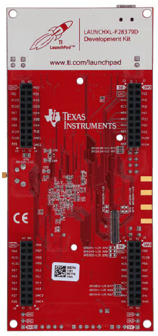
The DSP F28379D controller, manufactured by Texas Instruments, is a high-performance digital signal processor designed for real-time control applications. It features dual-core C28x CPUs and integrated peripherals, making it ideal for advanced motor control, power conversion, and industrial automation. This documentation provides a comprehensive guide to understanding, using, and troubleshooting the F28379D controller.

Explore Projects Built with DSP F28379D controller

Use Cirkit Designer to design, explore, and prototype these projects online. Some projects support real-time simulation. Click "Open Project" to start designing instantly!
DSP F28379D Controller-Based Dual Pushbutton Interface with Resistors
Image of Dsp controller: A project utilizing DSP F28379D controller in a practical application
This circuit features a DSP F28379D microcontroller interfaced with two pushbuttons and two resistors. The pushbuttons are connected to the GPIO pins of the microcontroller, allowing for user input, while the resistors are used for pull-down purposes to ensure stable logic levels.
Cirkit Designer LogoOpen Project in Cirkit Designer
ESP32-Based Smart Security System with Fingerprint Access and Audio Feedback
Image of fingerprint_KA: A project utilizing DSP F28379D controller in a practical application
This circuit features an ESP32 microcontroller interfaced with a DFPlayer Mini MP3 player module, a TFT LCD display, a fingerprint scanner, and multiple pushbuttons. The ESP32 controls a 12V solenoid lock and communicates with the DFPlayer Mini to play audio through a connected piezo speaker. The circuit is designed to create an access control system with user interaction through buttons, visual feedback via the TFT display, and audio prompts or alarms through the speaker.
Cirkit Designer LogoOpen Project in Cirkit Designer
ESP32-Based RFID Music Player with Arcade Button Controls
Image of Robot Music Player: A project utilizing DSP F28379D controller in a practical application
This circuit features an ESP32 Devkit V1 microcontroller interfaced with a DFPlayer Mini MP3 player module, an RFID-RC522 reader, a piezo speaker, and two arcade buttons. The ESP32 controls audio playback through the DFPlayer Mini, which is connected to the speaker, and uses the RFID reader to trigger specific audio tracks based on RFID tag data. The arcade buttons are used to control playback and adjust volume, while a rocker switch and battery mount provide power management.
Cirkit Designer LogoOpen Project in Cirkit Designer
ESP32-S3 Controlled Multi-Channel Relay System with ULN2803 Darlington Arrays
Image of rollladensteuerung: A project utilizing DSP F28379D controller in a practical application
This circuit features an ESP32-S3 microcontroller connected to multiple ULN2803 Darlington Array ICs, which are used to drive higher current loads. The ESP32-S3's GPIO pins are interfaced with the input pins of the Darlington arrays, suggesting that the microcontroller is controlling a series of external devices, likely inductive loads such as motors or relays. Additionally, an LM2596 Step Down Module is connected to the ESP32-S3, providing a regulated voltage supply to the microcontroller.
Cirkit Designer LogoOpen Project in Cirkit Designer

Explore Projects Built with DSP F28379D controller

Use Cirkit Designer to design, explore, and prototype these projects online. Some projects support real-time simulation. Click "Open Project" to start designing instantly!
Image of Dsp controller: A project utilizing DSP F28379D controller in a practical application
DSP F28379D Controller-Based Dual Pushbutton Interface with Resistors
This circuit features a DSP F28379D microcontroller interfaced with two pushbuttons and two resistors. The pushbuttons are connected to the GPIO pins of the microcontroller, allowing for user input, while the resistors are used for pull-down purposes to ensure stable logic levels.
Cirkit Designer LogoOpen Project in Cirkit Designer
Image of fingerprint_KA: A project utilizing DSP F28379D controller in a practical application
ESP32-Based Smart Security System with Fingerprint Access and Audio Feedback
This circuit features an ESP32 microcontroller interfaced with a DFPlayer Mini MP3 player module, a TFT LCD display, a fingerprint scanner, and multiple pushbuttons. The ESP32 controls a 12V solenoid lock and communicates with the DFPlayer Mini to play audio through a connected piezo speaker. The circuit is designed to create an access control system with user interaction through buttons, visual feedback via the TFT display, and audio prompts or alarms through the speaker.
Cirkit Designer LogoOpen Project in Cirkit Designer
Image of Robot Music Player: A project utilizing DSP F28379D controller in a practical application
ESP32-Based RFID Music Player with Arcade Button Controls
This circuit features an ESP32 Devkit V1 microcontroller interfaced with a DFPlayer Mini MP3 player module, an RFID-RC522 reader, a piezo speaker, and two arcade buttons. The ESP32 controls audio playback through the DFPlayer Mini, which is connected to the speaker, and uses the RFID reader to trigger specific audio tracks based on RFID tag data. The arcade buttons are used to control playback and adjust volume, while a rocker switch and battery mount provide power management.
Cirkit Designer LogoOpen Project in Cirkit Designer
Image of rollladensteuerung: A project utilizing DSP F28379D controller in a practical application
ESP32-S3 Controlled Multi-Channel Relay System with ULN2803 Darlington Arrays
This circuit features an ESP32-S3 microcontroller connected to multiple ULN2803 Darlington Array ICs, which are used to drive higher current loads. The ESP32-S3's GPIO pins are interfaced with the input pins of the Darlington arrays, suggesting that the microcontroller is controlling a series of external devices, likely inductive loads such as motors or relays. Additionally, an LM2596 Step Down Module is connected to the ESP32-S3, providing a regulated voltage supply to the microcontroller.
Cirkit Designer LogoOpen Project in Cirkit Designer

Technical Specifications

Key Technical Details

Parameter Value
Manufacturer Texas Instruments
Part Number F28379D
CPU Dual-core C28x CPUs
Operating Voltage 1.2V (Core), 3.3V (I/O)
Clock Speed Up to 200 MHz
Flash Memory 1 MB
RAM 204 KB
ADC Channels 24
PWM Channels 24
Communication Interfaces SPI, I2C, UART, CAN, USB
Operating Temperature -40°C to 125°C

Pin Configuration and Descriptions

Pin Number Pin Name Description
1 VDD Core supply voltage (1.2V)
2 VSS Ground
3 GPIO0 General-purpose I/O
4 GPIO1 General-purpose I/O
5 ADCIN0 Analog-to-digital converter input
6 ADCIN1 Analog-to-digital converter input
7 PWM1 Pulse-width modulation output
8 PWM2 Pulse-width modulation output
9 SPI_MOSI SPI Master Out Slave In
10 SPI_MISO SPI Master In Slave Out
11 I2C_SCL I2C Clock Line
12 I2C_SDA I2C Data Line
13 UART_TX UART Transmit
14 UART_RX UART Receive
15 CAN_TX CAN Transmit
16 CAN_RX CAN Receive
17 USB_DM USB Data Minus
18 USB_DP USB Data Plus
19 RESET Reset
20 XCLKIN External clock input

Usage Instructions

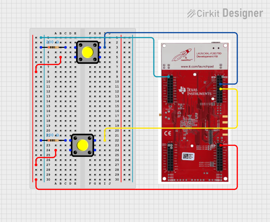
How to Use the Component in a Circuit

  1. Power Supply:

    • Connect the VDD pin to a 1.2V power supply for the core voltage.
    • Connect the VSS pin to the ground.
    • Ensure the I/O voltage is 3.3V.
  2. Clock Configuration:

    • Connect an external clock source to the XCLKIN pin if required.
    • Configure the internal PLL for the desired operating frequency.
  3. Peripheral Connections:

    • Connect ADC inputs to the ADCIN pins.
    • Connect PWM outputs to the PWM pins.
    • Use SPI, I2C, UART, and CAN pins for communication interfaces.
  4. Programming:

    • Use Texas Instruments' Code Composer Studio (CCS) for programming.
    • Load the firmware via JTAG or other supported programming interfaces.

Important Considerations and Best Practices

  • Power Supply: Ensure stable and clean power supply to avoid noise and instability.
  • Decoupling Capacitors: Place decoupling capacitors close to the power pins to filter out noise.
  • Grounding: Use a solid ground plane to minimize electromagnetic interference (EMI).
  • Clock Source: Use a high-quality clock source for accurate timing and synchronization.
  • Heat Dissipation: Ensure proper heat dissipation, especially in high-power applications.

Troubleshooting and FAQs

Common Issues Users Might Face

  1. Power Issues:

    • Symptom: The controller does not power up.
    • Solution: Check the power supply connections and ensure the correct voltage levels.
  2. Clock Configuration:

    • Symptom: The controller is not running at the expected speed.
    • Solution: Verify the clock source and PLL configuration.
  3. Peripheral Communication:

    • Symptom: Communication interfaces (SPI, I2C, UART, CAN) are not working.
    • Solution: Check the pin connections and ensure proper initialization in the firmware.
  4. ADC Readings:

    • Symptom: Incorrect or noisy ADC readings.
    • Solution: Ensure proper grounding and shielding of analog signals. Use appropriate filtering.

Solutions and Tips for Troubleshooting

  • Debugging Tools: Use an oscilloscope or logic analyzer to monitor signals and diagnose issues.
  • Firmware Debugging: Utilize the debugging features in Code Composer Studio to step through the code and identify problems.
  • Documentation: Refer to the Texas Instruments datasheet and reference manual for detailed information and guidelines.

Example Code for Arduino UNO

While the F28379D is not typically used with an Arduino UNO, here is an example of how you might interface the two using UART communication:

// Arduino UNO code to communicate with F28379D via UART

void setup() {
  Serial.begin(9600); // Initialize UART communication at 9600 baud rate
}

void loop() {
  if (Serial.available()) {
    char data = Serial.read(); // Read data from F28379D
    Serial.print("Received: ");
    Serial.println(data); // Print received data
  }
  
  // Send data to F28379D
  Serial.print("Hello F28379D");
  delay(1000); // Wait for 1 second
}

Conclusion

The DSP F28379D controller from Texas Instruments is a versatile and powerful component for real-time control applications. By following the guidelines and best practices outlined in this documentation, users can effectively integrate and utilize the F28379D in their projects. For further information, refer to the official Texas Instruments datasheet and reference manual.